Nissan Pathfinder (2006 year). Manual - part 38
REPAIR FOR COMPONENT PARTS
AT-295
D
E
F
G
H
I
J
K
L
M
A
B
AT
2006 Pathfinder
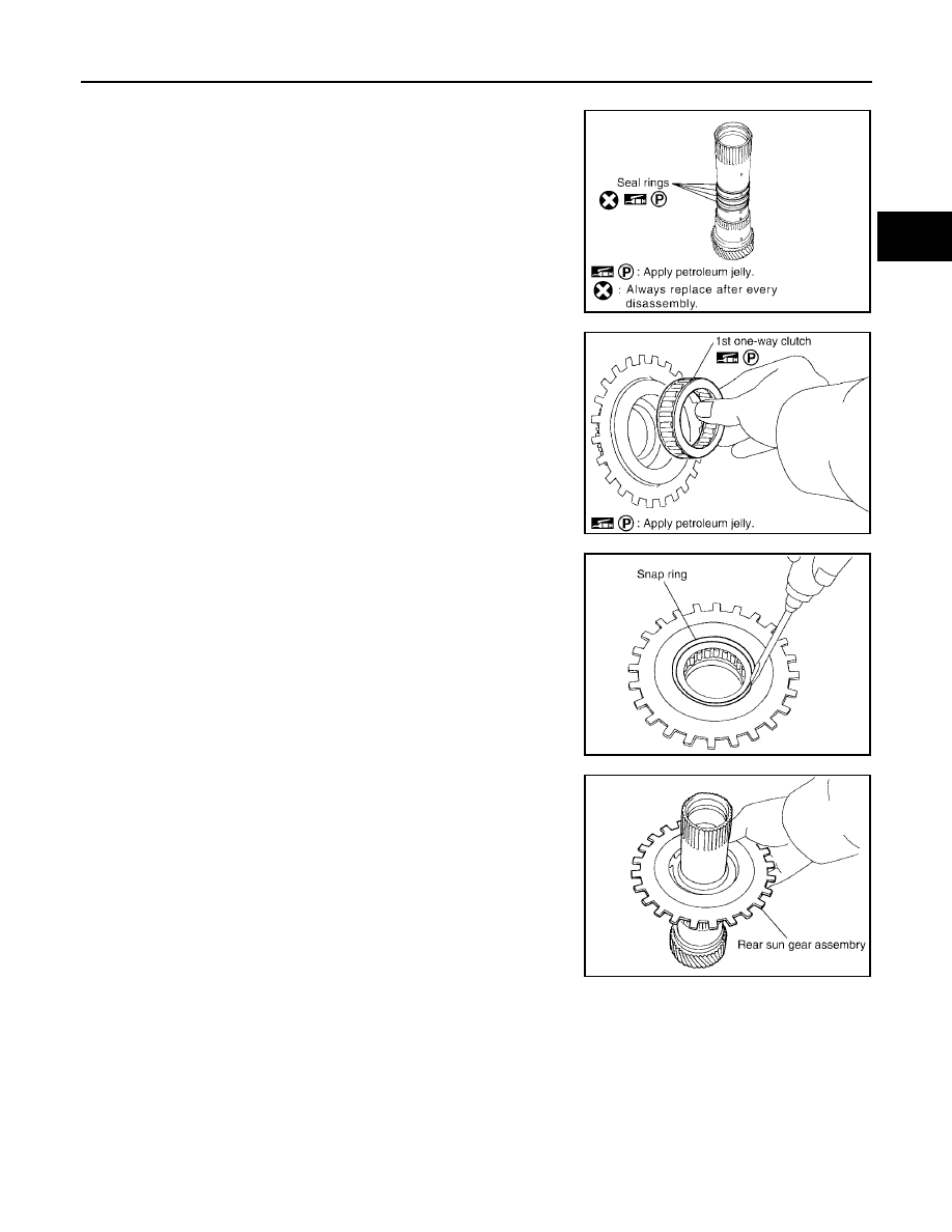
ASSEMBLY
1.
Install seal rings to mid sun gear.
CAUTION:
●
Do not reuse seal rings.
●
Apply petroleum jelly to seal rings.
2.
Install 1st one-way clutch to rear sun gear.
CAUTION:
Apply petroleum jelly to 1st one-way clutch.
3.
Install snap ring to rear sun gear using suitable tool.
4.
Install rear sun gear assembly to mid sun gear assembly.
SCIA2861E
SCIA4633E
SCIA2859E
SCIA2858E