Nissan Pathfinder (2005 year). Manual - part 353


  Index      Manuals     Nissan Pathfinder (2005 year) - Service and Repair Manual


Search            copyright infringement  


Content      ..     351      352      353      354     ..


Nissan Pathfinder (2005 year). Manual - part 353


PREPARATION

MTC-15

C

D

E

F

G

H

I

K

L

M

A

B

MTC

2005 Pathfinder

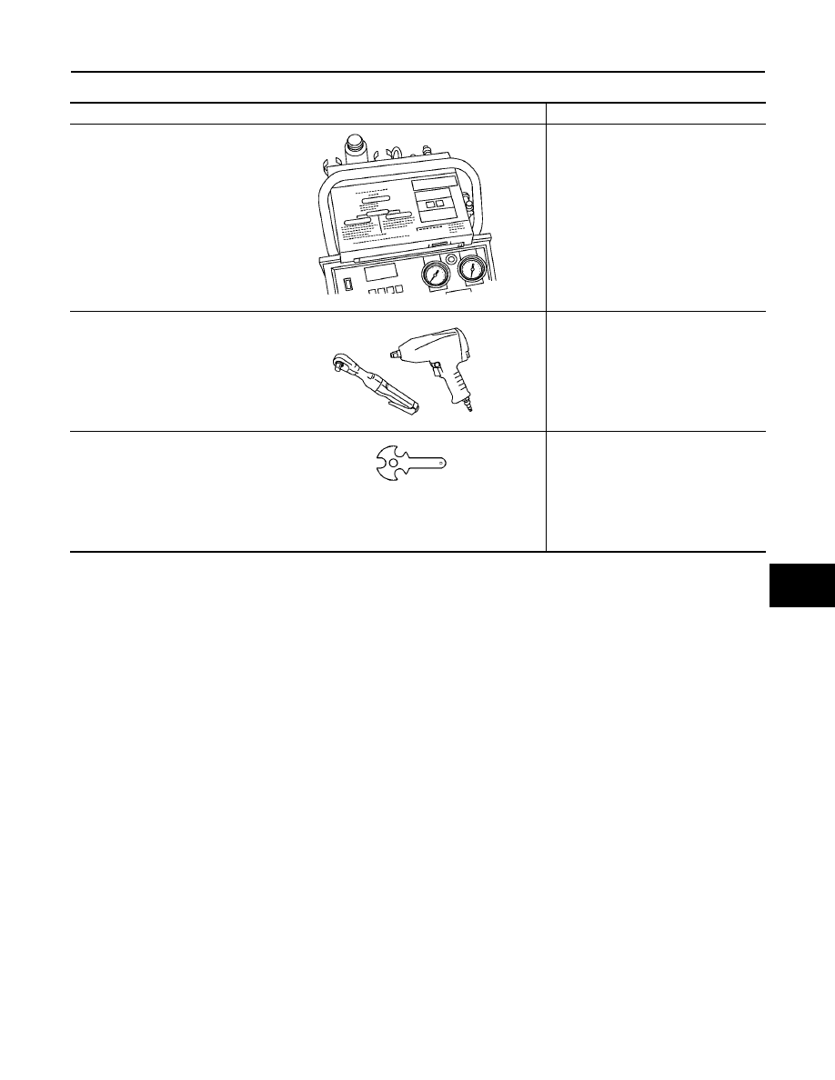
Commercial Service Tools

EJS003UW

Tool name

Description

(J-41810-NI)
Refrigerant identifier equipment (R-
134a)

For checking refrigerant purity and
system contamination

Power tool

Loosening bolts and nuts

(J-44614)
Clutch disc holding tool

Clutch disc holding tool

RJIA0197E

PBIC0190E

WHA230

MTC-16

REFRIGERATION SYSTEM

2005 Pathfinder

REFRIGERATION SYSTEM

PFP:KA990

Components

EJS003UX

REFRIGERATION SYSTEM

LJIA0155E

REFRIGERATION SYSTEM

MTC-17

C

D

E

F

G

H

I

K

L

M

A

B

MTC

2005 Pathfinder

Refrigerant Cycle

EJS003UY

REFRIGERANT FLOW

The refrigerant flows in the standard pattern. Refrigerant flows through the compressor, condenser, liquid tank,
expansion valve, evaporator, and back to the compressor. The refrigerant evaporation through the evaporator
coil is controlled by an externally equalized expansion valve, located inside the evaporator case.

FREEZE PROTECTION

The compressor cycles on and off to maintain the evaporator temperature within a specified range. When the
evaporator coil temperature falls below a specified point, the intake sensor interrupts the compressor opera-
tion. When the evaporator coil temperature rises above the specification, the intake sensor allows compressor
operation.

Refrigerant System Protection

EJS003UZ

REFRIGERANT PRESSURE SENSOR

The refrigerant system is protected against excessively high- or low-pressures by the refrigerant pressure sen-
sor, located on the condenser. If the system pressure rises above or falls below the specifications, the refriger-
ant pressure sensor detects the pressure inside the refrigerant line and sends a voltage signal to the ECM.
The ECM de-energizes the A/C relay to disengage the magnetic compressor clutch when pressure on the high
pressure side detected by refrigerant pressure sensor is over about 2,746 kPa (28 kg/cm

2

, 398 psi), or below

about 120 kPa (1.22 kg/cm

2

, 17.4 psi).

1.

Defroster nozzle

2.

LH side demister duct

3.

LH ventilator duct

4.

RH side demister duct

5.

RH ventilator duct

6.

Center ventilator duct

7.

Front heater and cooling unit assembly

8.

Floor connector duct grilles

9.

Floor connector duct

10. Front ducts

11.

Floor ducts

12. Rear console duct

13. Center console duct

14. Front console duct

RJIA1552E

MTC-18

REFRIGERATION SYSTEM

2005 Pathfinder

PRESSURE RELIEF VALVE

The refrigerant system is also protected by a pressure relief valve, located in the rear head of the compressor.
When the pressure of refrigerant in the system increases to an abnormal level [more than 2,990 kPa (30.5 kg/
cm

2

, 433.6 psi)], the release port on the pressure relief valve automatically opens and releases refrigerant

into the atmosphere.

LUBRICANT

MTC-19

C

D

E

F

G

H

I

K

L

M

A

B

MTC

2005 Pathfinder

LUBRICANT

PFP:KLG00

Maintenance of Lubricant Quantity in Compressor

EJS003V0

The lubricant in the compressor circulates through the system with the refrigerant. Add lubricant to compres-
sor when replacing any component or after a large refrigerant leakage has occurred. It is important to maintain
the specified amount.
If lubricant quantity is not maintained properly, the following malfunctions may result:

Lack of lubricant: May lead to a seized compressor

Excessive lubricant: Inadequate cooling (thermal exchange interference)

LUBRICANT

Name: NISSAN A/C System Lubricant Type S (DH-PS) or equivalent.
Part number: KLH00-PAGS0.

CHECKING AND ADJUSTING

CAUTION:

If excessive lubricant leakage is noted, do not perform the lubricant return operation.
Start the engine and set the following conditions:

Test Condition

Engine speed: Idling to 1,200 rpm

A/C switch: On

Blower speed: Max. position

Temperature control: Optional [Set so that intake air temperature is 25

°

to 30

°

C (77

°

to 86

°

F)]

Intake position: Recirculation (

)

Perform lubricant return operation for about ten minutes

Adjust the lubricant quantity according to the following table.

Lubricant Adjusting Procedure for Components Replacement Except Compressor

After replacing any of the following major components, add the correct amount of lubricant to the system.

Amount of Lubricant to be Added

*1:

If refrigerant leak is small, no addition of lubricant is needed.

Lubricant Adjustment Procedure for Compressor Replacement

1.

Before connecting recovery/recycling equipment to vehicle, check recovery/recycling equipment gauges.
No refrigerant pressure should be displayed. If NG, recover refrigerant from equipment lines.

2.

Connect recovery/recycling equipment to vehicle. Confirm refrigerant purity in supply tank using recovery/
recycling equipment and refrigerant identifier. If NG, refer to

MTC-4, "Contaminated Refrigerant"

.

3.

Confirm refrigerant purity in vehicle A/C system using recovery/recycling equipment and refrigerant identi-
fier. If NG, refer to

MTC-4, "Contaminated Refrigerant"

.

4.

Discharge refrigerant into the refrigerant recovery/recycling equipment. Measure lubricant discharged into
the recovery/recycling equipment.

5.

Drain the lubricant from the “old” (removed) compressor into a graduated container and recover the
amount of lubricant drained.

6.

Drain the lubricant from the “new” compressor into a separate, clean container.

7.

Measure an amount of new lubricant installed equal to amount drained from “old” compressor. Add this
lubricant to “new” compressor through the suction port opening.

Part replaced

Lubricant to be added to system

Remarks

Amount of lubricant

m

(US fl oz, Imp fl oz)

Evaporator

75 (2.5, 2.6)

Condenser

75 (2.5, 2.6)

Liquid tank

5 (0.2, 0.2)

Add if compressor is not replaced.

In case of refrigerant leak

30 (1.0, 1.1)

Large leak

Small leak *1

MTC-20

LUBRICANT

2005 Pathfinder

8.

Measure an amount of new lubricant equal to the amount recovered during discharging. Add this lubricant
to “new” compressor through the suction port opening.

9.

If the liquid tank also needs to be replaced, add an additional 5 m

(0.2 US fl oz, 0.2 Imp fl oz) of lubricant

at this time.
Do not add this 5 m

(0.2 US fl oz, 0.2 Imp fl oz) of lubricant if only replacing the compressor.

RHA065DD

AIR CONDITIONER CONTROL

MTC-21

C

D

E

F

G

H

I

K

L

M

A

B

MTC

2005 Pathfinder

AIR CONDITIONER CONTROL

PFP:27500

Description

EJS003V1

The front air control provides regulation of the vehicle's interior temperature. The system is based on the posi-
tion of the front air controls temperature switch selected by the driver. This is done by utilizing a microcom-
puter, also referred to as the front air control, which receives input signals from the following two sensors:

Intake sensor

PBR (Position Balanced Resistor)

The front air control uses these signals (including the set position of the temperature switch) to control:

Outlet air volume

Air temperature

Air distribution

Operation

EJS003V2

AIR MIX DOOR CONTROL

The air mix door is controlled so that in-vehicle temperature changed based on the position of the temperature
switch.

BLOWER SPEED CONTROL

Blower speed is controlled based on front blower switch settings.
When blower switch is turned, the blower motor starts and increases air flow volume each time the blower
switch is turned counterclockwise, and decreases air flow volume each time the blower switch is turned coun-
terclockwise.
When engine coolant temperature is low, the blower motor operation is delayed to prevent cool air from flow-
ing.

INTAKE DOORS CONTROL

The intake doors are controlled by the recirculation switch setting, and the mode (defroster) switch setting.

MODE DOOR CONTROL

The mode door is controlled by the position of the mode switch.

DEFROSTER DOOR CONTROL

The defroster door is controlled by the defroster dial set to defroster.

MAGNET CLUTCH CONTROL

When the A/C switch is pressed, or the mode switch is turned to the defroster position, the front air control out-
puts a compressor ON signal to BCM.
The BCM then sends a compressor ON signal to ECM, via CAN communication line.

WJIA1293E

MTC-22

AIR CONDITIONER CONTROL

2005 Pathfinder

ECM judges whether compressor can be turned ON, based on each sensor status (refrigerant pressure sen-
sor signal, throttle angle sensor, etc.). If it judges compressor can be turned ON, it sends compressor ON sig-
nal to IPDM E/R, via CAN communication line.
Upon receipt of compressor ON signal from ECM, IPDM E/R turns air conditioner relay ON to operate com-
pressor.


Content      ..     351      352      353      354     ..