Nissan Pathfinder (2005 year). Manual - part 251


  Index      Manuals     Nissan Pathfinder (2005 year) - Service and Repair Manual


Search            copyright infringement  


Content      ..     249      250      251      252     ..


Nissan Pathfinder (2005 year). Manual - part 251


CYLINDER BLOCK

EM-113

C

D

E

F

G

H

I

J

K

L

M

A

EM

2005 Pathfinder

i.

Apply new engine oil to threads and seat surfaces of the bolts.

ii.

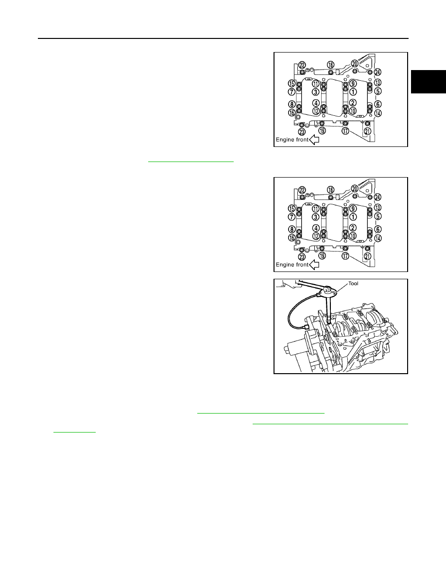
Tighten M8 bolts in numerical order as shown from No. 17 to 24.

CAUTION:

Wipe off completely any protruding liquid gasket on rear oil
seal installation surface.

NOTE:
There are more processes to complete the tightening bolts.
However stop procedure here to install rear oil seal.

c.

Install rear oil seal. Refer to

EM-90, "INSTALLATION"

.

d.

Restart tightening of lower cylinder block bolts as follows:

i.

Tighten M10 bolts in numerical order as shown from No. 1 to 16.

NOTE:
Use TORX socket (size E14) for bolts No. 1 to 16 (M10 bolt).

ii.

Turn M10 bolts 90

°

clockwise in numerical order from No. 1 to

16 using Tool.

CAUTION:

Use angle wrench Tool to check tightening angle. Do not
make judgement by visual inspection.

After installing the bolts, make sure that crankshaft can be rotated smoothly by hand.

Wipe off completely any protruding liquid gasket on front side of the engine.

Check the crankshaft end play. Refer to

EM-122, "CRANKSHAFT END PLAY"

.

8.

Inspect the outer diameter of connecting rod bolt. Refer to

EM-131, "CONNECTING ROD BOLT OUTER

DIAMETER"

.

9.

Install piston to connecting rod as follows:

a.

Install new snap ring to the groove of piston rear side using suitable tool.

Insert it fully into groove to install.

b.

Install piston to connecting rod.

Using industrial use drier or similar tool, heat piston until piston pin can be pushed in by hand without
excess force [approx. 60

°

to 70

°

C (140

°

to 158

°

F)]. From the front to the rear, insert piston pin into pis-

ton and connecting rod.

Bolts 17 - 24

: 22.1 N·m (2.3 kg-m, 16 ft-lb)

PBIC2941E

Bolts 1 - 16

: 35.3 N·m (3.6 kg-m, 26 ft-lb)

PBIC2941E

Tool number

: KV10112100 (BT-8653-A)

WBIA0584E

EM-114

CYLINDER BLOCK

2005 Pathfinder

Assemble so that the front mark on the piston head and the
cylinder number on connecting rod are positioned as shown.

c.

Install new snap ring to the groove of the piston front side.

Insert it fully into groove to install.

After installing, make sure that connecting rod moves
smoothly.

10. Install piston rings using piston ring expander or suitable tool.

CAUTION:

When installing piston rings, be careful not to damage
piston.

Be careful not to damage piston rings by expending them
excessively.

If there is stamped mark on ring, mount it with marked side
up.

NOTE:
If there is no stamp on ring, no specific orientation is required
for installation.

Position each ring with the gap as shown referring to the pis-
ton front mark.

Check the piston ring side clearance. Refer to

EM-123, "PISTON RING SIDE CLEARANCE"

.

11. Install connecting rod bearings to connecting rod and connecting rod bearing cap.

Before installing connecting rod bearings, apply engine oil to the bearing surface (inside). Do not apply
engine oil to the back surface, but thoroughly clean it.

SEM838F

PBIC0087E

Stamped mark:

Top ring

: —

Second ring

: R

SEM757G

PBIC0808E

CYLINDER BLOCK

EM-115

C

D

E

F

G

H

I

J

K

L

M

A

EM

2005 Pathfinder

When installing, align connecting rod bearing stopper protru-
sion with cutout of connecting rods and connecting rod bear-
ing caps to install.

Ensure the oil hole on connecting rod and that on the corre-
sponding bearing are aligned.

12. Install piston and connecting rod assembly to crankshaft.

13. Position crankshaft pin corresponding to connecting rod to be installed onto the bottom dead center.

14. Apply engine oil sufficiently to the cylinder bore, piston and crankshaft pin journal.

15. Match the cylinder position with the cylinder number on connecting rod to install.

NOTE:
Be sure that front mark on piston head is facing front of engine.

16. Install piston with the front mark on the piston head facing the

front of engine using Tool.

CAUTION:

Be careful not to damage the cylinder wall and crankshaft
pin, resulting from an interference of the connecting rod big
end.

17. Install connecting rod bearing cap.

Match the stamped cylinder number marks on connecting rod
with those on connecting rod bearing cap to install.

Be sure that front mark on connecting rod bearing cap is fac-
ing front of engine.

18. Tighten connecting rod bolts as follows:

a.

Apply engine oil to the threads and seats of connecting rod bolts.

b.

Tighten connecting rod bolts.

PBIC2067E

Tool number

: EM03470000 (J-8037)

WBIA0585E

PBIC0809E

Connecting rod bolt

: 19.6 N·m (2.0 kg-m, 14 ft-lb)

EM-116

CYLINDER BLOCK

2005 Pathfinder

c.

Then tighten all connecting rod bolts 90

°

clockwise.

CAUTION:

Always use Tool. Avoid tightening based on visual check
alone.

After tightening connecting rod bolts, make sure that crank-
shaft rotates smoothly.

Check the connecting rod side clearance. Refer to

EM-122,

"CONNECTING ROD SIDE CLEARANCE"

.

19. Install pilot converter (A/T models).

With drift of the following outer diameter, press-fit as far as it
will go.

Press-fit pilot converter with its chamfer facing crankshaft as
shown. (A/T models)

20. Install knock sensors.

Install knock sensor so that connector faces rear of engine.

After installing knock sensor, connect harness connector, and
lay it out to rear of engine.

CAUTION:

Do not tighten bolts while holding connector.

If any impact by dropping is applied to knock sensor,
replace it with new one.

NOTE:

Make sure that there is no foreign material on the cylinder
block mating surface and the back surface of knock sensor.

Make sure that knock sensor does not interfere with other
parts.

Tool number

: KV10112100 (BT-8653-A)

WBIA0586E

Pilot converter

: Approx. 33 mm (1.30 in)

PBIC2947E

SEM537E

PBIC2948E

CYLINDER BLOCK

EM-117

C

D

E

F

G

H

I

J

K

L

M

A

EM

2005 Pathfinder

21. Assemble in the reverse order of disassembly after this step.

Drive plate (A/T models)

Install drive plate and reinforcement plate as shown.

Holding ring gear using Tool.

Tighten bolts crosswise over several times.

How to Select Piston and Bearing

EBS00NK9

DESCRIPTION

*: For the service parts, the grade for fitting cannot be selected between piston pin and connecting rod. (Only “0” grade is available.) The

information at the shipment from the plant is described as a reference.

The identification grade stamped on each part is the grade for the dimension measured in new condition.
This grade cannot apply to reused parts.

For reused or repaired parts, measure the dimension accurately. Determine the grade by comparing the
measurement with the values of each selection table.

For details of the measurement method of each part, the reuse standards and the selection method of the
selective fitting parts, refer to the text.

HOW TO SELECT PISTON
When New Cylinder Block is Used

Check the cylinder bore grade (“1”, “2”, or “3”) on rear side of cylin-
der block, and select piston of the same grade.
NOTE:
Piston is available with piston pin as a set for the service part. (Only
“0” grade piston pin is available.)

When Cylinder Block is Reused

1.

Measure the cylinder bore inner diameter. Refer to

EM-126, "Cylinder Bore Inner Diameter"

.

Tool number

: KV10117700 (J-44716)

PBIC0910E

Selection points

Selection parts

Selection items

Selection methods

Between cylinder block and
crankshaft

Main bearing

Main bearing grade
(bearing thickness)

Determined by match of cylin-
der block bearing housing
grade (inner diameter of hous-
ing) and crankshaft journal
grade (outer diameter of jour-
nal)

Between crankshaft and con-
necting rod

Connecting rod bearing

Connecting rod bearing grade
(bearing thickness)

Combining service grades for
connecting rod big end diame-
ter and crankshaft pin outer
diameter determine connecting
rod bearing selection.

Between cylinder block and pis-
ton

Piston and piston pin assembly
(Piston is available together
with piston pin as assembly.)

Piston grade
(piston skirt diameter)

Piston grade = cylinder bore
grade (inner diameter of bore)

Between piston and connecting
rod*

PBIC2949E

EM-118

CYLINDER BLOCK

2005 Pathfinder

2.

Determine the bore grade by comparing the measurement with
the values under the cylinder bore inner diameter of the “Piston
Selection Table”.

3.

Select piston of the same grade.

Piston Selection Table

Unit: mm (in)

NOTE:

Piston is available together with piston pin as assembly.

Piston pin (piston pin hole) grade is provided only for the parts installed at the plant. For service parts, no
piston pin grades can be selected. (Only “0” grade is available.)

No second grade mark is available on piston.

HOW TO SELECT CONNECTING ROD BEARING
When New Connecting Rod and Crankshaft are Used

Check pin journal grade (“0”, “1”, or “2”) on front of crankshaft, and
select connecting rod bearing of the same grade.

NOTE:
There is no grading for connecting rod big end diameter.

When Crankshaft and Connecting Rod are Reused

1.

Measure the connecting rod big end diameter. Refer to

EM-124, "CONNECTING ROD BIG END DIAME-

TER"

.

2.

Make sure that the connecting rod big end diameter is within the standard value.

3.

Measure the crankshaft pin journal diameter. Refer to

EM-128, "CRANKSHAFT PIN JOURNAL DIAME-

TER"

.

4.

Determine the grade of crankshaft pin journal grade by corresponding to the measured dimension in
“Crankshaft pin journal diameter” column of “Connecting Rod Bearing Selection Table”.

5.

Select connecting rod bearing of the same grade.

Connecting Rod Bearing Selection Table

Unit: mm (in)

PBIC2950E

Grade

1

2 (or no mark)

3

Cylinder bore inner diameter

95.500 - 95.510

(3.7598 - 3.7602)

95.510 - 95.520

(3.7602 - 3.7606)

95.520 - 95.530

(3.7606 - 3.7610)

Piston skirt diameter

95.480 - 95.490

(3.7590 - 3.7594)

95.490 - 95.500

(3.7594 - 3.7598)

95.500 - 95.510

(3.7598 - 3.7602)

PBIC2951E

Connecting rod big end diameter

57.000 - 57.013 (2.2441 - 2.2446)

CYLINDER BLOCK

EM-119

C

D

E

F

G

H

I

J

K

L

M

A

EM

2005 Pathfinder

Unit: mm (in)

Undersize Bearings Usage Guide

When the specified connecting rod bearing oil clearance is not obtained with standard size connecting rod
bearings, use undersize (US) bearings.

When using undersize (US) bearing, measure the connecting rod bearing inner diameter with bearing
installed, and grind crankshaft pin so that the connecting rod bearing oil clearance satisfies the standard.

CAUTION:

In grinding crankshaft pin to use undersize bearings, keep
the fillet R [1.5 - 1.7 mm (0.059 - 0.067 in)].

Bearing undersize table

Unit: mm (in)

HOW TO SELECT MAIN BEARING
When New Cylinder Block and Crankshaft are Used

1.

“Main Bearing Selection Table” rows correspond to bearing
housing grade on rear left side of cylinder block.

2.

“Main Bearing Selection Table” columns correspond to journal
diameter grade on front side of crankshaft.

Crankshaft

Connecting rod bearing

Crankshaft pin journal diameter

Grade (Mark)

Dimension (Bearing thickness range)

Bearing grade No.

Color

53.968 - 53.974 (2.1247 - 2.1250)

0

1.500 - 1.503 (0.0591 - 0.0592)

STD 0

Black

53.962 - 53.968 (2.1245 - 2.1247)

1

1.503 - 1.506 (0.0592 - 0.0593)

STD 1

Brown

53.956 - 53.962 (2.1242 - 2.1245)

2

1.506 - 1.509 (0.0593 - 0.0594)

STD 2

Green

PBIC1908E

Size

Thickness

US 0.25 (0.0098)

1.626 - 1.634 (0.0640 - 0.0643)

PBIC2949E

PBIC2951E

EM-120

CYLINDER BLOCK

2005 Pathfinder

3.

Select main bearing grade at the point where selected row and column meet in “Main Bearing Selection
Table”.

When Cylinder Block and Crankshaft are Reused

1.

Measure cylinder block main bearing housing inner diameter and crankshaft main journal diameter. Refer
to

EM-126, "MAIN BEARING HOUSING INNER DIAMETER"

and

EM-127, "CRANKSHAFT MAIN JOUR-

NAL DIAMETER"

.

2.

Correspond the measured dimension in “Cylinder block main bearing housing inner diameter” row of
“Main Bearing Selection Table”.

3.

Correspond the measured dimension in “Crankshaft main journal diameter” column of “Main Bearing
Selection Table”.

4.

Select main bearing grade at the point where selected row and column meet in following selection table.

Main Bearing Selection Table

WBIA0625E


Content      ..     249      250      251      252     ..