Nissan Pathfinder (2005 year). Manual - part 218


  Index      Manuals     Nissan Pathfinder (2005 year) - Service and Repair Manual


Search            copyright infringement  


Content      ..     216      217      218      219     ..


Nissan Pathfinder (2005 year). Manual - part 218


DTC P1554 BATTERY CURRENT SENSOR

EC-595

C

D

E

F

G

H

I

J

K

L

M

A

EC

2005 Pathfinder

6.

CHECK BATTERY CURRENT SENSOR INPUT SIGNAL CIRCUIT FOR OPEN AND SHORT

1.

Check harness continuity between battery current sensor terminal 3 and ECM terminal 71.

2.

Also check harness for short to ground and short to power.

OK or NG

OK

>> GO TO 8.

NG

>> GO TO 7.

7.

DETECT MALFUNCTIONING PART

Check the following.

Harness connectors E5, F14

Harness for open or short between battery current sensor and ECM

>> Repair open circuit or short to ground or short to power in harness or connectors.

8.

CHECK BATTERY CURRENT SENSOR

Refer to

EC-595, "Component Inspection"

.

OK or NG

OK

>> GO TO 9.

NG

>> Replace battery negative cable assembly.

9.

CHECK INTERMITTENT INCIDENT

Refer to

EC-158, "TROUBLE DIAGNOSIS FOR INTERMITTENT INCIDENT"

.

>> INSPECTION END

Component Inspection

UBS00KU4

BATTERY CURRENT SENSOR

1.

Reconnect harness connectors disconnected.
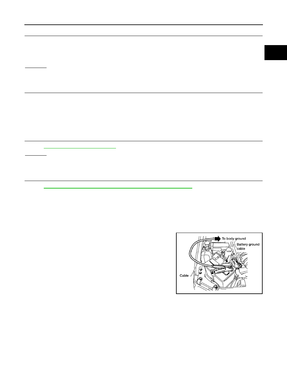
2.

Disconnect battery negative cable.

3.

Install jumper cable between battery negative terminal and body
ground.

4.

Turn ignition switch ON.

Continuity should exist.

BBIA0588E

EC-596

DTC P1554 BATTERY CURRENT SENSOR

2005 Pathfinder

5.

Check voltage between ECM terminal 71 (battery current sensor
signal) and ground.

6.

If NG, replace battery negative cable assembly.

Voltage: Approximately 2.5V

PBIB2617E

DTC P1564 ASCD STEERING SWITCH

EC-597

C

D

E

F

G

H

I

J

K

L

M

A

EC

2005 Pathfinder

DTC P1564 ASCD STEERING SWITCH

PFP:25551

Component Description

UBS00KFV

ASCD steering switch has variant values of electrical resistance for each button. ECM reads voltage variation
of switch, and determines which button is operated.

Refer to

EC-30, "AUTOMATIC SPEED CONTROL DEVICE (ASCD)"

for the ASCD function.

CONSULT-II Reference Value in Data Monitor Mode

UBS00KFW

Specification data are reference values.

On Board Diagnosis Logic

UBS00KFX

This self-diagnosis has the one trip detection logic.
The MIL will not light up for this diagnosis.

NOTE:
If DTC P1564 is displayed with DTC P0605, first perform the trouble diagnosis for DTC P0605. Refer to

EC-396

.

PBIB2645E

MONITOR ITEM

CONDITION

SPECIFICATION

MAIN SW

Ignition switch: ON

MAIN switch: Pressed

ON

MAIN switch: Released

OFF

CANCEL SW

Ignition switch: ON

CANCEL switch: Pressed

ON

CANCEL switch: Released

OFF

RESUME/ACC SW

Ignition switch: ON

RESUME/ACCELERATE switch:
Pressed

ON

RESUME/ACCELERATE switch:
Released

OFF

SET SW

Ignition switch: ON

SET/COAST switch: Pressed

ON

SET/COAST switch: Released

OFF

DTC No.

Trouble Diagnosis

Name

DTC Detecting Condition

Possible Cause

P1564
1564

ASCD steering
switch

An excessively high voltage signal from the ASCD
steering switch is sent to ECM.

ECM detects that input signal from the ASCD
steering switch is out of the specified range.

ECM detects that the ASCD steering switch is
stuck ON.

Harness or connectors
(The switch circuit is open or shorted.)

ASCD steering switch

ECM

EC-598

DTC P1564 ASCD STEERING SWITCH

2005 Pathfinder

DTC Confirmation Procedure

UBS00KFY

NOTE:
If DTC Confirmation Procedure has been previously conducted, always turn ignition switch OFF and wait at
least 10 seconds before conducting the next test.

WITH CONSULT-II

1.

Turn ignition switch ON.

2.

Select “DATA MONITOR” mode with CONSULT-II.

3.

Wait at least 10 seconds.

4.

Press MAIN switch for at least 10 seconds, then release it and
wait at least 10 seconds.

5.

Press CANCEL switch for at least 10 seconds, then release it
and wait at least 10 seconds.

6.

Press RESUME/ACCELERATE switch for at least 10 seconds,
then release it and wait at least 10 seconds.

7.

Press SET/COAST switch for at least 10 seconds, then release
it and wait at least 10 seconds.

8.

If DTC is detected, go to

EC-600, "Diagnostic Procedure"

.

WITH GST

Follow the procedure “WITH CONSULT-II” above.

SEF058Y

DTC P1564 ASCD STEERING SWITCH

EC-599

C

D

E

F

G

H

I

J

K

L

M

A

EC

2005 Pathfinder

Wiring Diagram

UBS00KFZ

BBWA1765E

EC-600

DTC P1564 ASCD STEERING SWITCH

2005 Pathfinder

Specification data are reference values and are measured between each terminal and ground.

CAUTION:

Do not use ECM ground terminals when measuring input/output voltage. Doing so may result in dam-
age to the ECM's transistor. Use a ground other than ECM terminals, such as the ground.

Diagnostic Procedure

UBS00KG0

1.

CHECK GROUND CONNECTIONS

1.

Turn ignition switch OFF.

2.

Loosen and retighten three ground screws on the body. Refer to

EC-165, "Ground Inspection"

.

OK or NG

OK

>> GO TO 2.

NG

>> Repair or replace ground connections.

TER-

MINAL

NO.

WIRE

COLOR

ITEM

CONDITION

DATA (DC Voltage)

67

B

Sensor ground

[Engine is running]

Warm-up condition

Idle speed

Approximately 0V

99

SB

ASCD steering switch

[Ignition switch: ON]

ASCD steering switch: OFF

Approximately 4V

[Ignition switch: ON]

MAIN switch: Pressed

Approximately 0V

[Ignition switch: ON]

CANCEL switch: Pressed

Approximately 1V

[Ignition switch: ON]

RESUME/ACCELERATE switch: Pressed

Approximately 3V

[Ignition switch: ON]

SET/COAST switch: Pressed

Approximately 2V

BBIA0539E

DTC P1564 ASCD STEERING SWITCH

EC-601

C

D

E

F

G

H

I

J

K

L

M

A

EC

2005 Pathfinder

2.

CHECK ASCD STEERING SWITCH CIRCUIT

With CONSULT-II

1.

Turn ignition switch ON.

2.

Select “MAIN SW”, “RESUME/ACC SW”, “SET SW” and “CANCEL SW” in “DATA MONITOR” mode with
CONSULT-II.

3.

Check each item indication under the following conditions.

Without CONSULT-II

1.

Turn ignition switch ON.

2.

Check voltage between ECM terminal 99 and ground with press-
ing each button.

OK or NG

OK

>> GO TO 8.

NG

>> GO TO 3.

3.

CHECK ASCD STEERING SWITCH GROUND CIRCUIT FOR OPEN AND SHORT

1.

Turn ignition switch OFF.

2.

Disconnect combination switch harness connector.

3.

Disconnect ECM harness connector.

4.

Check harness continuity between combination switch terminal 17 and ECM terminal 67. Refer to Wiring
Diagram.

5.

Also check harness for short to ground and short to power.

OK or NG

OK

>> GO TO 5.

NG

>> GO TO 4.

Switch

Monitor item

Condition

Indication

MAIN switch

MAIN SW

Pressed

ON

Released

OFF

CANCEL switch

CANCEL SW

Pressed

ON

Released

OFF

RESUME/ACCELER-
ATE switch

RESUME/ACC SW

Pressed

ON

Released

OFF

SET/COAST switch

SET SW

Pressed

ON

Released

OFF

SEC006D

Switch

Condition

Voltage [V]

MAIN switch

Pressed

Approx. 0

Released

Approx. 4

CANCEL switch

Pressed

Approx. 1

Released

Approx. 4

RESUME/ACCELERATE
switch

Pressed

Approx. 3

Released

Approx. 4

SET/COAST switch

Pressed

Approx. 2

Released

Approx. 4

PBIB0311E

Continuity should exist.

EC-602

DTC P1564 ASCD STEERING SWITCH

2005 Pathfinder

4.

DETECT MALFUNCTIONING PART

Check the following.

Harness connectors M31, E152

Harness connectors E5, F14

Combination switch (spiral cable)

Harness for open and short between ECM and combination switch

>> Repair open circuit or short to ground or short to power in harness or connectors.

5.

CHECK ASCD STEERING SWITCH INPUT SIGNAL CIRCUIT FOR OPEN AND SHORT

1.

Check harness continuity between ECM terminal 99 and combination switch terminal 18.
Refer to Wiring Diagram.

2.

Also check harness for short to ground and short to power.

OK or NG

OK

>> GO TO 7.

NG

>> GO TO 6.

6.

DETECT MALFUNCTIONING PART

Check the following.

Harness connectors M31, E152

Combination switch (spiral cable)

Harness for open and short between ECM and combination switch

>> Repair open circuit or short to ground or short to power in harness or connectors.

7.

CHECK ASCD STEERING SWITCH

Refer to

EC-603, "Component Inspection"

.

OK or NG

OK

>> GO TO 8.

NG

>> Replace steering wheel.

8.

CHECK INTERMITTENT INCIDENT

Refer to

EC-158, "TROUBLE DIAGNOSIS FOR INTERMITTENT INCIDENT"

.

>> INSPECTION END

Continuity should exist.


Content      ..     216      217      218      219     ..