Nissan Pathfinder (2005 year). Manual - part 197


  Index      Manuals     Nissan Pathfinder (2005 year) - Service and Repair Manual


Search            copyright infringement  


Content      ..     195      196      197      198     ..


Nissan Pathfinder (2005 year). Manual - part 197


DTC P1124, P1126 THROTTLE CONTROL MOTOR RELAY

EC-427

C

D

E

F

G

H

I

J

K

L

M

A

EC

2005 Pathfinder

With GST

Follow the procedure “With CONSULT-II” above.

PROCEDURE FOR DTC P1126
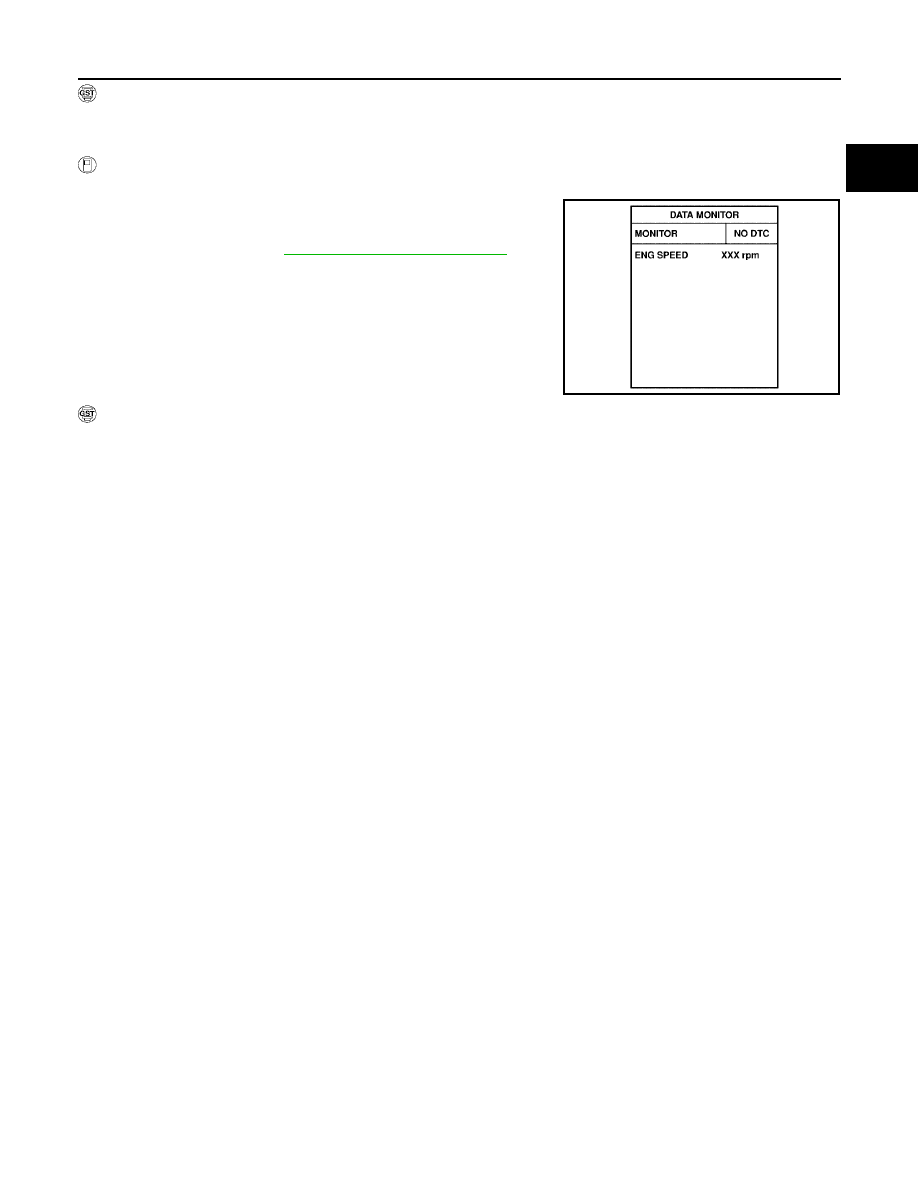
With CONSULT-II

1.

Turn ignition switch ON and wait at least 2 seconds.

2.

Select “DATA MONITOR””mode with CONSULT-II.

3.

Start engine and let it idle for 5 seconds.

4.

If DTC is detected, go to

EC-429, "Diagnostic Procedure"

.

With GST

Follow the procedure “With CONSULT-II” above.

SEF058Y

EC-428

DTC P1124, P1126 THROTTLE CONTROL MOTOR RELAY

2005 Pathfinder

Wiring Diagram

UBS00KCG

BBWA1760E

DTC P1124, P1126 THROTTLE CONTROL MOTOR RELAY

EC-429

C

D

E

F

G

H

I

J

K

L

M

A

EC

2005 Pathfinder

Specification data are reference values and are measured between each terminal and ground.

CAUTION:

Do not use ECM ground terminals when measuring input/output voltage. Doing so may result in dam-
age to the ECM's transistor. Use a ground other than ECM terminals, such as the ground.

Diagnostic Procedure

UBS00KCH

1.

CHECK THROTTLE CONTROL MOTOR RELAY POWER SUPPLY CIRCUIT-I

1.

Turn ignition switch OFF.

2.

Check voltage between ECM terminal 104 and ground with
CONSULT-II or tester.

OK or NG

OK

>> GO TO 4.

NG

>> GO TO 2.

2.

CHECK THROTTLE CONTROL MOTOR RELAY POWER SUPPLY CIRCUIT-II

1.

Disconnect ECM harness connector.

2.

Disconnect IPDM E/R harness connector E122.

3.

Check continuity between ECM terminal 104 and IPDM E/R terminal 47.
Refer to Wiring Diagram.

4.

Also check harness for short to ground and short to power.

OK or NG

OK

>> GO TO 3.

NG

>> Repair open circuit or short to ground or short to power in harness or connectors.

3.

CHECK FUSE

1.

Disconnect 20A fuse.

2.

Check 20A fuse for blown.

OK or NG

OK

>> GO TO 7.

NG

>> Replace 20A fuse.

TER-

MINAL

NO.

WIRE

COLOR

ITEM

CONDITION

DATA (DC Voltage)

3

V

Throttle control motor relay
power supply

[Ignition switch: ON]

BATTERY VOLTAGE
(11 - 14V)

104

O

Throttle control motor relay

[Ignition switch: OFF]

BATTERY VOLTAGE
(11 - 14V)

[Ignition switch: ON]

0 - 1.0V

Voltage: Battery voltage

PBIB1171E

Continuity should exist.

EC-430

DTC P1124, P1126 THROTTLE CONTROL MOTOR RELAY

2005 Pathfinder

4.

CHECK THROTTLE CONTROL MOTOR RELAY INPUT SIGNAL CIRCUIT-I

1.

Check voltage between ECM terminal 3 and ground under the
following conditions with CONSULT-II or tester.

OK or NG

OK

>> GO TO 7.

NG

>> GO TO 5.

5.

CHECK THROTTLE CONTROL MOTOR RELAY INPUT SIGNAL CIRCUIT-II

1.

Turn ignition switch OFF.

2.

Disconnect ECM harness connector.

3.

Disconnect IPDM E/R harness connector E119.

4.

Check continuity between ECM terminal 3 and IPDM E/R terminal 6.
Refer to Wiring Diagram.

5.

Also check harness for short to ground and short to power.

OK or NG

OK

>> GO TO 7.

NG

>> GO TO 6.

6.

DETECT MALFUNCTIONING PART

Check the following.

Harness connectors E2, F32

Harness for open or short between ECM and IPDM E/R

>> Repair open circuit or short to ground or short to power in harness or connectors.

7.

CHECK INTERMITTENT INCIDENT

Refer to

EC-158, "TROUBLE DIAGNOSIS FOR INTERMITTENT INCIDENT"

.

OK or NG

OK

>> Replace IPDM E/R. Refer to

PG-17, "IPDM E/R (INTELLIGENT POWER DISTRIBUTION MOD-

ULE ENGINE ROOM)"

.

NG

>> Repair or replace harness or connectors.

Ignition switch

Voltage

OFF

Approximately 0V

ON

Battery voltage

(11 - 14V)

MBIB0028E

Continuity should exist.

DTC P1128 THROTTLE CONTROL MOTOR

EC-431

C

D

E

F

G

H

I

J

K

L

M

A

EC

2005 Pathfinder

DTC P1128 THROTTLE CONTROL MOTOR

PFP:16119

Component Description

UBS00KCI

The throttle control motor is operated by the ECM and it opens and closes the throttle valve.
The current opening angle of the throttle valve is detected by the throttle position sensor and it provides feed-
back to the ECM to control the throttle control motor to make the throttle valve opening angle properly in
response to driving condition.

On Board Diagnosis Logic

UBS00KCJ

This self-diagnosis has the one trip detection logic.

FAIL-SAFE MODE

When the malfunction is detected, the ECM enters fail-safe mode and the MIL lights up.

DTC Confirmation Procedure

UBS00KCK

NOTE:
If DTC Confirmation Procedure has been previously conducted, always turn ignition switch OFF and wait at
least 10 seconds before conducting the next test.

WITH CONSULT-II

1.

Turn ignition switch ON and wait at least 2 seconds.

2.

Select “DATA MONITOR” mode with CONSULT-II.

3.

Start engine and let it idle for 5 seconds.

4.

If DTC is detected, go to

EC-433, "Diagnostic Procedure"

.

WITH GST

Follow the procedure “WITH CONSULT-II” above.

DTC No.

Trouble diagnosis name

DTC detecting condition

Possible cause

P1128
1128

Throttle control motor
circuit short

ECM detects short in both circuits between
ECM and throttle control motor.

Harness or connectors
(Throttle control motor circuit is shorted.)

Electric throttle control actuator
(Throttle control motor)

Engine operating condition in fail-safe mode

ECM stops the electric throttle control actuator control, throttle valve is maintained at a fixed opening (approx. 5 degrees) by the return
spring.

SEF058Y

EC-432

DTC P1128 THROTTLE CONTROL MOTOR

2005 Pathfinder

Wiring Diagram

UBS00KCL

BBWA1761E

DTC P1128 THROTTLE CONTROL MOTOR

EC-433

C

D

E

F

G

H

I

J

K

L

M

A

EC

2005 Pathfinder

Specification data are reference values and are measured between each terminal and ground.
Pulse signal is measured by CONSULT-II.

CAUTION:

Do not use ECM ground terminals when measuring input/output voltage. Doing so may result in dam-
age to the ECM's transistor. Use a ground other than ECM terminals, such as the ground.

: Average voltage for pulse signal (Actual pulse signal can be confirmed by oscilloscope.)

Diagnostic Procedure

UBS00KCM

1.

CHECK GROUND CONNECTIONS

1.

Turn ignition switch OFF.

2.

Loosen and retighten three ground screws on the body. Refer to

EC-165, "Ground Inspection"

.

OK or NG

OK

>> GO TO 2.

NG

>> Repair or replace ground connections.

TER-

MINAL

NO.

WIRE

COLOR

ITEM

CONDITION

DATA (DC Voltage)

4

L/W

Throttle control motor
(Close)

[Ignition switch: ON]

Engine: Stopped

Shift lever: D

Accelerator pedal: Released

0 - 14V

5

L/B

Throttle control motor
(Open)

[Ignition switch: ON]

Engine: Stopped

Shift lever: D

Accelerator pedal: Fully depressed

0 - 14V

PBIB1104E

PBIB1105E

BBIA0539E

EC-434

DTC P1128 THROTTLE CONTROL MOTOR

2005 Pathfinder

2.

CHECK THROTTLE CONTROL MOTOR OUTPUT SIGNAL CIRCUIT FOR OPEN OR SHORT

1.

Disconnect electric throttle control actuator harness connector.

2.

Disconnect ECM harness connector.

3.

Check harness continuity between the following terminals.
Refer to Wiring Diagram.

4.

Also check harness for short to ground and short to power.

OK or NG

OK

>> GO TO 3.

NG

>> Repair or replace.

3.

CHECK THROTTLE CONTROL MOTOR

Refer to

EC-434, "Component Inspection"

.

OK or NG

OK

>> GO TO 4.

NG

>> GO TO 5.

4.

CHECK INTERMITTENT INCIDENT

Refer to

EC-158, "TROUBLE DIAGNOSIS FOR INTERMITTENT INCIDENT"

.

OK or NG

OK

>> GO TO 5.

NG

>> Repair or replace harness or connectors.

5.

REPLACE ELECTRIC THROTTLE CONTROL ACTUATOR

1.

Replace the electric throttle control actuator.

2.

Perform

EC-88, "Throttle Valve Closed Position Learning"

.

3.

Perform

EC-89, "Idle Air Volume Learning"

.

>> INSPECTION END

Component Inspection

UBS00KCN

THROTTLE CONTROL MOTOR

1.

Disconnect electric throttle control actuator harness connector.

2.

Check resistance between terminals 5 and 6.

3.

If NG, replace electric throttle control actuator and go to next
step.

4.

Perform

EC-88, "Throttle Valve Closed Position Learning"

.

5.

Perform

EC-89, "Idle Air Volume Learning"

.

Electric throttle control

actuator terminal

ECM terminal

Continuity

5

5

Should not exist

4

Should exist

6

5

Should exist

4

Should not exist

BBIA0543E

Resistance: Approximately 1 - 15

[at 25

°

C (77

°

F)]

PBIB2606E


Content      ..     195      196      197      198     ..