Nissan Pathfinder (2005 year). Manual - part 187
DTC P0451 EVAP CONTROL SYSTEM PRESSURE SENSOR
EC-347
C
D
E
F
G
H
I
J
K
L
M
A
EC
2005 Pathfinder
DTC Confirmation Procedure
UBS00K9O
NOTE:
If DTC Confirmation Procedure has been previously conducted, always turn ignition switch OFF and wait at
least 10 seconds before conducting the next test.
WITH CONSULT-II
1.
Turn ignition switch OFF and wait at least 10 seconds.
2.
Turn ignition switch ON and select “DATA MONITOR” mode with
CONSULT-II.
3.
Start engine and wait at least 40 seconds.
NOTE:
Do not depress accelerator pedal even slightly.
If 1st trip DTC is detected, go to
EC-347, "Diagnostic Procedure"
.
WITH GST
Follow the procedure “WITH CONSULT-II” above.
Diagnostic Procedure
UBS00K9P
1.
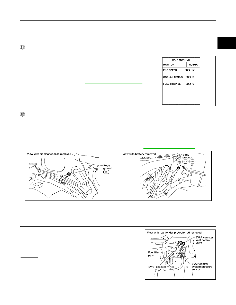
CHECK GROUND CONNECTIONS
1.
Turn ignition switch OFF.
2.
Loosen and retighten three ground screws on the body. Refer to
.
OK or NG
OK
>> GO TO 2.
NG
>> Repair or replace ground connections.
2.
CHECK EVPA CONTROL SYSTEM PRESSURE SENSOR CONNECTOR FOR WATER
1.
Disconnect EVAP control system pressure sensor harness con-
nector.
2.
Check sensor harness connector for water.
OK or NG
OK
>> GO TO 3.
NG
>> Repair or replace harness connector.
SEF194Y
BBIA0539E
Water should not exist.
BBIA0551E