Nissan Pathfinder (2005 year). Manual - part 151


  Index      Manuals     Nissan Pathfinder (2005 year) - Service and Repair Manual


Search            copyright infringement  


Content      ..     149      150      151      152     ..


Nissan Pathfinder (2005 year). Manual - part 151


ON BOARD DIAGNOSTIC (OBD) SYSTEM

EC-59

C

D

E

F

G

H

I

J

K

L

M

A

EC

2005 Pathfinder

The time required for each diagnosis varies with road surface conditions, weather, altitude, individual driv-
ing habits, etc.
Zone A refers to the range where the time, required for the diagnosis under normal conditions*, is the
shortest.
Zone B refers to the range where the diagnosis can still be performed if the diagnosis is not completed
within zone A.

*: Normal conditions refer to the following:

Sea level

Flat road

Ambient air temperature: 20 - 30

°

C (68 - 86

°

F)

Diagnosis is performed as quickly as possible under normal conditions.
Under different conditions [For example: ambient air temperature other than 20 - 30

°

C (68 - 86

°

F)], diag-

nosis may also be performed.

Pattern 1:

The engine is started at the engine coolant temperature of

10 to 35

°

C (14 to 95

°

F)

(where the voltage between the ECM terminal 73 and ground is 3.0 - 4.3V).

The engine must be operated at idle speed until the engine coolant temperature is greater than
70

°

C (158

°

F) (where the voltage between the ECM terminal 73 and ground is lower than 1.4V).

The engine is started at the fuel tank temperature of warmer than 0

°

C (32

°

F) (where the voltage

between the ECM terminal 107 and ground is less than 4.1V).

Pattern 2:

When steady-state driving is performed again even after it is interrupted, each diagnosis can be con-
ducted. In this case, the time required for diagnosis may be extended.
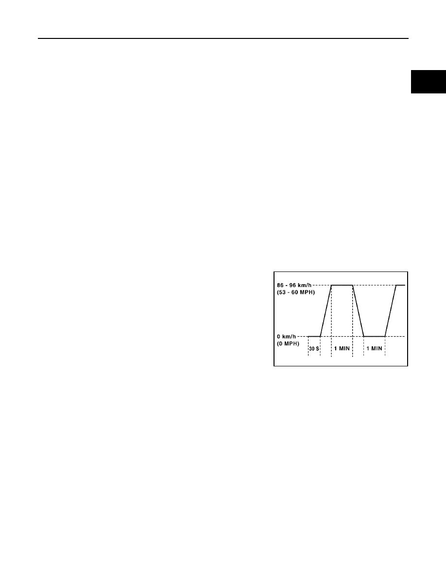
Pattern 3:

Operate vehicle following the driving pattern shown in the figure.

replace the accelerator pedal during decelerating vehicle speed
from 90km/h (56MPH) to 0km/h (0MPH).

Pattern 4:

The accelerator pedal must be held very steady during steady-
state driving.

If the accelerator pedal is moved, the test must be conducted all
over again.

*1: Depress the accelerator pedal until vehicle speed is 90 km/h (56
MPH), then release the accelerator pedal and keep it released for
more than 10 seconds. Depress the accelerator pedal until vehicle
speed is 90 km/h (56 MPH) again.
*2: Checking the vehicle speed with GST is advised.

Suggested Transmission Gear Position
Set the selector lever in the D position.

TEST VALUE AND TEST LIMIT (GST ONLY — NOT APPLICABLE TO CONSULT-II)

The following is the information specified in Service $06 of SAE J1979.
The test value is a parameter used to determine whether a system/circuit diagnostic test is OK or NG while
being monitored by the ECM during self-diagnosis. The test limit is a reference value which is specified as the
maximum or minimum value and is compared with the test value being monitored.
These data (test value and test limit) are specified by Test ID (TID) and Component ID (CID) and can be dis-
played on the GST screen.

PBIB2244E

EC-60

ON BOARD DIAGNOSTIC (OBD) SYSTEM

2005 Pathfinder

Item

Self-diagnostic test item

DTC

Test value

(GST display)

Test limit

Conversion

TID

CID

CATALYST

Three way catalyst function (Bank 1)

P0420

01H

01H

Max.

1/128

P0420

02H

81H

Min.

1

Three way catalyst function (Bank 2)

P0430

03H

02H

Max.

1/128

P0430

04H

82H

Min.

1

EVAP SYSTEM

EVAP control system (Small leak)

P0442

05H

03H

Max.

1/128mm

2

EVAP control system purge flow monitoring

P0441

06H

83H

Min.

20mV

EVAP control system (Very small leak)

P0456

07H

03H

Max.

1/128mm

2

HO2S

Air fuel ratio (A/F) sensor 1 (Bank 1)

P1271

41H

8EH

Min.

5 mV

P1272

42H

0EH

Max.

5 mV

P1273

43H

0EH

Max.

0.002

P1274

44H

8EH

Min.

0.002

P1278

45H

8EH

Min.

0.004

P1276

46H

0EH

Max.

5 mV

P1276

47H

8EH

Min.

5 mV

P1279

48H

8EH

Min.

0.004

Air fuel ratio (A/F) sensor 1 (Bank 2)

P1281

4CH

8FH

Min.

5 mV

P1282

4DH

0FH

Max.

5 mV

P1283

4EH

0FH

Max.

0.002

P1284

4FH

8FH

Min.

0.002

P1288

50H

8FH

Min.

0.004

P1286

51H

0FH

Max.

5 mV

P1286

52H

8FH

Min.

5 mV

P1289

53H

8FH

Min.

0.004

Heated oxygen sensor 2 (Bank 1)

P0139

19H

86H

Min.

10mV/500ms

P1147

1AH

86H

Min.

10mV

P1146

1BH

06H

Max.

10mV

P0138

1CH

06H

Max.

10mV

Heated oxygen sensor 2 (Bank 2)

P0159

21H

87H

Min.

10mV/500ms

P1167

22H

87H

Min.

10mV

P1166

23H

07H

Max.

10mV

P0158

24H

07H

Max.

10mV

HO2S HEATER

Air fuel ratio (A/F) sensor 1 heater (Bank 1)

P1032

57H

10H

Max.

5 mV

P1031

58H

90H

Min.

5 mV

Air fuel ratio (A/F) sensor 1 heater (Bank 2)

P1052

59H

11H

Max.

5 mV

P1051

5AH

91H

Min.

5 mV

Heated oxygen sensor 2 heater (Bank 1)

P0038

2DH

0AH

Max.

20mV

P0037

2EH

8AH

Min.

20mV

Heated oxygen sensor 2 heater (Bank 2)

P0058

2FH

0BH

Max.

20mV

P0057

30H

8BH

Min.

20mV

ON BOARD DIAGNOSTIC (OBD) SYSTEM

EC-61

C

D

E

F

G

H

I

J

K

L

M

A

EC

2005 Pathfinder

HOW TO ERASE EMISSION-RELATED DIAGNOSTIC INFORMATION
How to Erase DTC

With CONSULT-II

The emission related diagnostic information in the ECM can be erased by selecting “ERASE” in the “SELF-
DIAG RESULTS” mode with CONSULT-II.
If DTCs are displayed for both ECM and TCM (Transmission control module), they need to be erased individu-
ally from the ECM and TCM (Transmission control module).

NOTE:
If the DTC is not for A/T related items (see

EC-9

), skip steps 2 through 4.

1.

If the ignition switch stays ON after repair work, be sure to turn ignition switch OFF once. Wait at least 10
seconds and then turn it ON (engine stopped) again.

2.

Turn CONSULT-II ON and touch “A/T”.

3.

Touch “SELF-DIAG RESULTS”.

4.

Touch “ERASE”. [The DTC in the TCM (Transmission control module) will be erased.] Then touch “BACK”
twice.

5.

Touch “ENGINE”.

6.

Touch “SELF-DIAG RESULTS”.

7.

Touch “ERASE”. (The DTC in the ECM will be erased.)

With GST

The emission related diagnostic information in the ECM can be erased by selecting Service $04 with GST.

NOTE:
If the DTC is not for A/T related items (see

EC-9

), skip step 2.

1.

If the ignition switch stays ON after repair work, be sure to turn ignition switch OFF once. Wait at least 10
seconds and then turn it ON (engine stopped) again.

SCIA5671E

EC-62

ON BOARD DIAGNOSTIC (OBD) SYSTEM

2005 Pathfinder

2.

Perform

AT-39, "HOW TO ERASE DTC (WITH GST)"

. (The DTC in TCM will be erased.)

3.

Select Service $04 with GST (Generic Scan Tool).

No Tools

NOTE:
If the DTC is not for A/T related items (see

EC-9

), skip step 2.

1.

If the ignition switch stays ON after repair work, be sure to turn ignition switch OFF once.
Wait at least 10 seconds and then turn it ON (engine stopped) again.

2.

Perform

AT-40, "HOW TO ERASE DTC (NO TOOLS)"

. (The DTC in TCM will be erased.)

3.

Change the diagnostic test mode from Mode II to Mode I by depressing the accelerator pedal. Refer to

EC-63, "HOW TO SWITCH DIAGNOSTIC TEST MODE"

.

If the battery is disconnected, the emission-related diagnostic information will be lost within 24
hours.

The following data are cleared when the ECM memory is erased.

Diagnostic trouble codes

1st trip diagnostic trouble codes

Freeze frame data

1st trip freeze frame data

System readiness test (SRT) codes

Test values

Actual work procedures are explained using a DTC as an example. Be careful so that not only the DTC, but all
of the data listed above, are cleared from the ECM memory during work procedures.

Malfunction Indicator Lamp (MIL)

UBS00K3T

DESCRIPTION

The MIL is located on the instrument panel.

1.

The MIL will light up when the ignition switch is turned ON with-
out the engine running. This is a bulb check.
If the MIL does not light up, refer to

DI-33, "WARNING LAMPS"

,

or see

EC-707

.

2.

When the engine is started, the MIL should go off.
If the MIL remains on, the on board diagnostic system has
detected an engine system malfunction.

SEF217U

ON BOARD DIAGNOSTIC (OBD) SYSTEM

EC-63

C

D

E

F

G

H

I

J

K

L

M

A

EC

2005 Pathfinder

ON BOARD DIAGNOSTIC SYSTEM FUNCTION

The on board diagnostic system has the following three functions.

When there is an open circuit on MIL circuit, the ECM cannot warn the driver by lighting up MIL when there is
malfunction on engine control system.
Therefore, when electrical controlled throttle and part of ECM related diagnoses are continuously detected as
NG for 5 trips, ECM warns the driver that engine control system malfunctions and MIL circuit is open by means
of operating fail-safe function.
The fail-safe function also operates when above diagnoses except MIL circuit are detected and demands the
driver to repair the malfunction.

MIL Flashing Without DTC

When any SRT codes are not set, MIL may flash without DTC. For the details, refer to

EC-57, "How to Display

SRT Status"

.

HOW TO SWITCH DIAGNOSTIC TEST MODE

NOTE:

It is better to count the time accurately with a clock.

It is impossible to switch the diagnostic mode when an accelerator pedal position sensor circuit
has a malfunction.

Always ECM returns to Diagnostic Test Mode I after ignition switch is turned OFF.

How to Set Diagnostic Test Mode II (Self-diagnostic Results)

1.

Confirm that accelerator pedal is fully released, turn ignition switch ON and wait 3 seconds.

2.

Repeat the following procedure quickly five times within 5 seconds.

a.

Fully depress the accelerator pedal.

b.

Fully release the accelerator pedal.

3.

Wait 7 seconds, fully depress the accelerator pedal and keep it for approx. 10 seconds until the MIL starts
blinking.

Diagnostic Test
Mode

KEY and ENG.
Status

Function

Explanation of Function

Mode I

Ignition switch in
ON position

Engine stopped

BULB CHECK

This function checks the MIL bulb for damage (blown,
open circuit, etc.).
If the MIL does not come on, check MIL circuit.

Engine running

MALFUNCTION
WARNING

This is a usual driving condition. When a malfunction is
detected twice in two consecutive driving cycles (two trip
detection logic), the MIL will light up to inform the driver
that a malfunction has been detected.
The following malfunctions will light up or blink the MIL in
the 1st trip.

Misfire (Possible three way catalyst damage)

One trip detection diagnoses

Mode II

Ignition switch in
ON position

Engine stopped

SELF-DIAGNOSTIC
RESULTS

This function allows DTCs and 1st trip DTCs to be read.

Engine operating condition in fail-safe mode

Engine speed will not rise more than 2,500 rpm due to the fuel cut

EC-64

ON BOARD DIAGNOSTIC (OBD) SYSTEM

2005 Pathfinder

NOTE:
Do not release the accelerator pedal for 10 seconds if MIL may start blinking on the halfway of this
10 seconds. This blinking is displaying SRT status and is continued for another 10 seconds. For
the details, refer to

EC-57, "How to Set SRT Code"

.

4.

Fully release the accelerator pedal.
ECM has entered to Diagnostic Test Mode II (Self-diagnostic results).

NOTE:
Wait until the same DTC (or 1st trip DTC) appears to confirm all DTCs certainly.

How to Erase Diagnostic Test Mode II (Self-diagnostic Results)

1.

Set ECM in Diagnostic Test Mode II (Self-diagnostic results). Refer to

EC-63, "How to Set Diagnostic Test

Mode II (Self-diagnostic Results)"

.

2.

Fully depress the accelerator pedal and keep it for more than 10 seconds.
The emission-related diagnostic information has been erased from the backup memory in the ECM.

3.

Fully release the accelerator pedal, and confirm the DTC 0000 is displayed.

DIAGNOSTIC TEST MODE I — BULB CHECK

In this mode, the MIL on the instrument panel should stay ON. If it remains OFF, check the bulb. Refer to

DI-

33, "WARNING LAMPS"

or see

EC-707

.

DIAGNOSTIC TEST MODE I — MALFUNCTION WARNING

This DTC number is clarified in Diagnostic Test Mode II (SELF-DIAGNOSTIC RESULTS)

DIAGNOSTIC TEST MODE II — SELF-DIAGNOSTIC RESULTS

In this mode, the DTC and 1st trip DTC are indicated by the number of blinks of the MIL as shown below.
The DTC and 1st trip DTC are displayed at the same time. If the MIL does not illuminate in diagnostic test
mode I (Malfunction warning), all displayed items are 1st trip DTCs. If only one code is displayed when the MIL
illuminates in diagnostic test mode II (SELF-DIAGNOSTIC RESULTS), it is a DTC; if two or more codes are
displayed, they may be either DTCs or 1st trip DTCs. DTC No. is same as that of 1st trip DTC. These uniden-

PBIB0092E

MIL

Condition

ON

When the malfunction is detected.

OFF

No malfunction.

ON BOARD DIAGNOSTIC (OBD) SYSTEM

EC-65

C

D

E

F

G

H

I

J

K

L

M

A

EC

2005 Pathfinder

tified codes can be identified by using the CONSULT-II or GST. A DTC will be used as an example for how to
read a code.

A particular trouble code can be identified by the number of four-digit numeral flashes. The “zero” is indicated
by the number of ten flashes. The length of time the 1,000th-digit numeral flashes on and off is 1.2 seconds
consisting of an ON (0.6-second) - OFF (0.6-second) cycle.
The 100th-digit numeral and lower digit numerals consist of a 0.3-second ON and 0.3-second OFF cycle.
A change from one digit numeral to another occurs at an interval of 1.0-second OFF. In other words, the later
numeral appears on the display 1.3 seconds after the former numeral has disappeared.
A change from one trouble code to another occurs at an interval of 1.8-second OFF.
In this way, all the detected malfunctions are classified by their DTC numbers. The DTC 0000 refers to no mal-
function. (See

EC-9, "INDEX FOR DTC"

)

How to Erase Diagnostic Test Mode II (Self-diagnostic Results)

The DTC can be erased from the back up memory in the ECM by depressing accelerator pedal. Refer to

EC-

63, "How to Set Diagnostic Test Mode II (Self-diagnostic Results)"

.

If the battery is disconnected, the DTC will be lost from the backup memory within 24 hours.

Be careful not to erase the stored memory before starting trouble diagnoses.

OBD System Operation Chart

UBS00K3U

RELATIONSHIP BETWEEN MIL, 1ST TRIP DTC, DTC, AND DETECTABLE ITEMS

When a malfunction is detected for the first time, the 1st trip DTC and the 1st trip freeze frame data are
stored in the ECM memory.

When the same malfunction is detected in two consecutive trips, the DTC and the freeze frame data are
stored in the ECM memory, and the MIL will come on. For details, refer to

EC-48, "Two Trip Detection

Logic"

.

The MIL will go off after the vehicle is driven 3 times with no malfunction. The drive is counted only when
the recorded driving pattern is met (as stored in the ECM). If another malfunction occurs while counting,
the counter will reset.

The DTC and the freeze frame data will be stored until the vehicle is driven 40 times (driving pattern A)
without the same malfunction recurring (except for Misfire and Fuel Injection System). For Misfire and
Fuel Injection System, the DTC and freeze frame data will be stored until the vehicle is driven 80 times
(driving pattern C) without the same malfunction recurring. The “TIME” in “SELF-DIAGNOSTIC
RESULTS” mode of CONSULT-II will count the number of times the vehicle is driven.

The 1st trip DTC is not displayed when the self-diagnosis results in OK for the 2nd trip.

PBIA3905E

EC-66

ON BOARD DIAGNOSTIC (OBD) SYSTEM

2005 Pathfinder

SUMMARY CHART

For details about patterns B and C under “Fuel Injection System” and “Misfire”, see

EC-68

.

For details about patterns A and B under Other, see

EC-70

.

*1: Clear timing is at the moment OK is detected.
*2: Clear timing is when the same malfunction is detected in the 2nd trip.

Items

Fuel Injection System

Misfire

Other

MIL (goes off)

3 (pattern B)

3 (pattern B)

3 (pattern B)

DTC, Freeze Frame Data (no
display)

80 (pattern C)

80 (pattern C)

40 (pattern A)

1st Trip DTC (clear)

1 (pattern C), *1

1 (pattern C), *1

1 (pattern B)

1st Trip Freeze Frame Data
(clear)

*1, *2

*1, *2

1 (pattern B)


Content      ..     149      150      151      152     ..