Nissan Pathfinder (2005 year). Manual - part 109


  Index      Manuals     Nissan Pathfinder (2005 year) - Service and Repair Manual


Search            copyright infringement  


Content      ..     107      108      109      110     ..


Nissan Pathfinder (2005 year). Manual - part 109


BODY REPAIR

BL-159

C

D

E

F

G

H

J

K

L

M

A

B

BL

2005 Pathfinder

1.

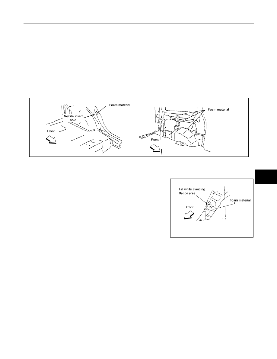
Fill procedures after installation of service part.

Remove foam material remaining on vehicle side.

Clean area in which foam was removed.

Install service part.

Insert nozzle into hole near fill area and fill foam material or fill in enough to close gap with the service
part.

2.

Fill procedures before installation of service part.

Remove foam material remaining on vehicle side.

Clean area in which foam was removed.

Fill foam material on wheelhouse outer side.

NOTE:
Fill in enough to close gap with service part while avoiding
flange area.

Install service part.

NOTE:
Refer to label for information on working times.

1.

Body side outer

2.

Body side insulation (foam)

3.

Rear wheel outer

4.

Side panel inner

5.

D-pillar inner reinforcement

6.

D-pillar outer reinforcement

7.

Roof

8.

Front roof rail

9.

Front roof rail brace

10. B-pillar inner

11.

B-pillar hinge brace

12. Rear side inner extension

13. D-pillar mail lower

LIIA1081E

LIIA1082E

BL-160

BODY REPAIR

2005 Pathfinder

Replacement Operations

EIS00416

DESCRIPTION

This section is prepared for technicians who have attained a high level of skill and experience in repairing col-
lision-damaged vehicles and also use modern service tools and equipment. Persons unfamiliar with body
repair techniques should not attempt to repair collision-damaged vehicles by using this section.

Technicians are also encouraged to read Body Repair Manual (Fundamentals) in order to ensure that the orig-
inal functions and quality of the vehicle can be maintained. The Body Repair Manual (Fundamentals) contains
additional information, including cautions and warnings, that are not including in this manual. Technicians
should refer to both manuals to ensure proper repairs.

Please note that this information is prepared for worldwide usage, and as such, certain procedures may not
apply in some regions or countries.

BODY REPAIR

BL-161

C

D

E

F

G

H

J

K

L

M

A

B

BL

2005 Pathfinder

The symbols used in this section for cutting and welding / brazing operations are shown below.

PIIA0149E

BL-162

BODY REPAIR

2005 Pathfinder

Front pillar butt joint can be determined anywhere within shaded
area as shown in the figure. The best location for the butt joint is
at position A due to the construction of the vehicle. Refer to the
front pillar section.

Determine cutting position and record distance from the locating
indent. Use this distance when cutting the service part. Cut outer
front pillar over 60 mm above inner front pillar cut position.

Prepare a cutting jig to make outer pillar easier to cut. Also, this
will permit service part to be accurately cut at joint position.

An example of cutting operation using a cutting jig is as follows.

1.

Mark cutting lines.
A: Cut position of outer pillar
B: Cut position of inner pillar

2.

Align cutting line with notch on jig. Clamp jig to pillar.

3.

Cut outer pillar along groove of jig. (At position A)

4.

Remove jig and cut remaining portions.

5.

Cut inner pillar at position B in same manner.

PIIA0150E

PIIA0151E

PIIA0152E

PIIA0153E

BODY REPAIR

BL-163

C

D

E

F

G

H

J

K

L

M

A

B

BL

2005 Pathfinder

HOODLEDGE
LH

Work after radiator core support has been removed.

LIIA1808E

BL-164

BODY REPAIR

2005 Pathfinder

RH

Work after radiator core support has been removed.

LIIA1809E

BODY REPAIR

BL-165

C

D

E

F

G

H

J

K

L

M

A

B

BL

2005 Pathfinder

FRONT PILLAR

Work after rear hoodledge reinforcement has been removed.

LIIA1810E

BL-166

BODY REPAIR

2005 Pathfinder

CENTER PILLAR

LIIA1811E


Content      ..     107      108      109      110     ..