Nissan Pathfinder (2005 year). Manual - part 6


  Index      Manuals     Nissan Pathfinder (2005 year) - Service and Repair Manual


Search            copyright infringement  


Content      ..     4      5      6      7     ..


Nissan Pathfinder (2005 year). Manual - part 6


A/T CONTROL SYSTEM

AT-19

D

E

F

G

H

I

J

K

L

M

A

B

AT

2005 Pathfinder

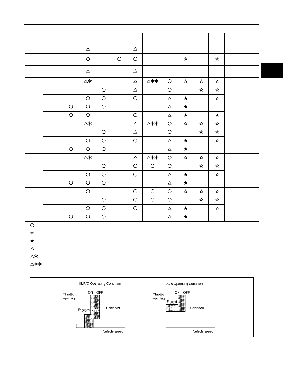
CLUTCH AND BAND CHART

—Operates

—Operates during “progressive” acceleration.

—Operates and effects power transmission while coasting.

—Line pressure is applied but does not affect power transmission.

—Operates under conditions shown in HLR/C Operating Condition

—Operates under conditions shown in LC/B Operating Condition. Delay control is applied during D (4,3,2,1)

Þ

N shift.

*1: A/T will not shift to 5th when overdrive control switch is set in “OFF” position.

Shift position

I/C

HLR/C

D/C

R/B

FR/B

LC/B

Fwd/B

1st

OWC

Fwd

OWC

3rd

OWC

Remarks

P

PARK POSITION

R

REVERSE POSI-

TION

N

NEUTRAL POSI-

TION

D*1

1st

Automatic shift

1

2

3

4

5

2nd

3rd

4th

5th

3

1st

Automatic shift

1

2

3

4

2nd

3rd

4th

2

1st

Automatic shift

1

2

3

4

2nd

3rd

4th

1

1st

Locks (held sta-

tionary in 1st

gear)

1

2

3

4

2nd

3rd

4th

SCIA5642E

AT-20

A/T CONTROL SYSTEM

2005 Pathfinder

POWER TRANSMISSION
“N” Position

Since both the forward brake and the reverse brake are released, torque from the input shaft drive is not trans-
mitted to the output shaft.

“P” Position

The same as for the “N” position, both the forward brake and the reverse brake are released, so torque
from the input shaft drive is not transmitted to the output shaft.

The parking pawl linked with the select lever meshes with the parking gear and fastens the output shaft
mechanically.

1.

Front brake

2.

Input clutch

3.

Direct clutch

4.

High and low reverse clutch

5.

Reverse brake

6.

Forward brake

7.

Low coast brake

8.

1st one-way clutch

9.

Forward one-way clutch

10. 3rd one-way clutch

11.

Front sun gear

12. Input shaft

13. Mid internal gear

14. Front internal gear

15. Rear carrier

16. Rear sun gear

17. Mid sun gear

18. Front carrier

19. Mid carrier

20. Rear internal gear

21. Output shaft

22. Parking gear

23. Parking pawl

PCIA0003J

A/T CONTROL SYSTEM

AT-21

D

E

F

G

H

I

J

K

L

M

A

B

AT

2005 Pathfinder

“D”, “3” and “2” Positions 1st Gear

The forward brake and the forward one-way clutch regulate reverse rotation of the mid sun gear.

The 1st one-way clutch regulates reverse rotation of the rear sun gear.

The 3rd one-way clutch regulates reverse rotation of the front sun gear.

During deceleration, the mid sun gear turns forward, so the forward one-way clutch idles and the engine
brake is not activated.

1.

Front brake

2.

Input clutch

3.

Direct clutch

4.

High and low reverse clutch

5.

Reverse brake

6.

Forward brake

7.

Low coast brake

8.

1st one-way clutch

9.

Forward one-way clutch

10. 3rd one-way clutch

11.

Front sun gear

12. Input shaft

13. Mid internal gear

14. Front internal gear

15. Rear carrier

16. Rear sun gear

17. Mid sun gear

18. Front carrier

19. Mid carrier

20. Rear internal gear

21. Output shaft

22. Parking gear

23. Parking pawl

SCIA1512E

AT-22

A/T CONTROL SYSTEM

2005 Pathfinder

“1 ” Position 1st Gear

The front brake fastens the front sun gear.

The forward brake and the forward one-way clutch regulate reverse rotation of the mid sun gear.

High and low reverse clutch connects the rear sun gear and the mid sun gear.

The low coast brake fastens the mid sun gear.

During deceleration, the low coast brake regulates forward rotation of the mid sun gear and the engine
brake functions.

1.

Front brake

2.

Input clutch

3.

Direct clutch

4.

High and low reverse clutch

5.

Reverse brake

6.

Forward brake

7.

Low coast brake

8.

1st one-way clutch

9.

Forward one-way clutch

10. 3rd one-way clutch

11.

Front sun gear

12. Input shaft

13. Mid internal gear

14. Front internal gear

15. Rear carrier

16. Rear sun gear

17. Mid sun gear

18. Front carrier

19. Mid carrier

20. Rear internal gear

21. Output shaft

22. Parking gear

23. Parking pawl

SCIA1513E

A/T CONTROL SYSTEM

AT-23

D

E

F

G

H

I

J

K

L

M

A

B

AT

2005 Pathfinder

“D” and “3” Positions 2nd Gear

The forward brake and the forward one-way clutch regulate reverse rotation of the mid sun gear.

The 3rd one-way clutch regulates reverse rotation of the front sun gear.

The direct clutch is coupled and the rear carrier and rear sun gear are connected.

During deceleration, the mid sun gear turns forward, so the forward one-way clutch idles and engine
brake is not activated.

1.

Front brake

2.

Input clutch

3.

Direct clutch

4.

High and low reverse clutch

5.

Reverse brake

6.

Forward brake

7.

Low coast brake

8.

1st one-way clutch

9.

Forward one-way clutch

10. 3rd one-way clutch

11.

Front sun gear

12. Input shaft

13. Mid internal gear

14. Front internal gear

15. Rear carrier

16. Rear sun gear

17. Mid sun gear

18. Front carrier

19. Mid carrier

20. Rear internal gear

21. Output shaft

22. Parking gear

23. Parking pawl

SCIA1514E

AT-24

A/T CONTROL SYSTEM

2005 Pathfinder

“2” and “1” Positions 2nd Gear

The front brake fastens the front sun gear.

The forward brake and the forward one-way clutch regulate reverse rotation of the mid sun gear.

The direct clutch is coupled, and the rear carrier and rear sun gear are connected.

The low coast brake fastens the mid sun gear.

During deceleration, the low coast brake regulates forward rotation of the mid sun gear and the engine
brake functions.

1.

Front brake

2.

Input clutch

3.

Direct clutch

4.

High and low reverse clutch

5.

Reverse brake

6.

Forward brake

7.

Low coast brake

8.

1st one-way clutch

9.

Forward one-way clutch

10. 3rd one-way clutch

11.

Front sun gear

12. Input shaft

13. Mid internal gear

14. Front internal gear

15. Rear carrier

16. Rear sun gear

17. Mid sun gear

18. Front carrier

19. Mid carrier

20. Rear internal gear

21. Output shaft

22. Parking gear

23. Parking pawl

SCIA1515E

A/T CONTROL SYSTEM

AT-25

D

E

F

G

H

I

J

K

L

M

A

B

AT

2005 Pathfinder

“D” and “3” Positions 3rd Gear

The front brake fastens the front sun gear.

The direct clutch is coupled, and the rear carrier and rear sun gear are connected.

The high and low reverse clutch is coupled and the mid sun gear and rear sun gear are connected.

1.

Front brake

2.

Input clutch

3.

Direct clutch

4.

High and low reverse clutch

5.

Reverse brake

6.

Forward brake

7.

Low coast brake

8.

1st one-way clutch

9.

Forward one-way clutch

10. 3rd one-way clutch

11.

Front sun gear

12. Input shaft

13. Mid internal gear

14. Front internal gear

15. Rear carrier

16. Rear sun gear

17. Mid sun gear

18. Front carrier

19. Mid carrier

20. Rear internal gear

21. Output shaft

22. Parking gear

23. Parking pawl

SCIA1516E

AT-26

A/T CONTROL SYSTEM

2005 Pathfinder

“D” Positions 4th Gear

The direct clutch is coupled, and the rear carrier and rear sun gear are connected.

The high and low reverse clutch is coupled and the mid sun gear and rear sun gear are connected.

The input clutch is coupled and the front internal gear and mid internal gear are connected.

The drive power is conveyed to the front internal gear, mid internal gear, and rear carrier and the three
planetary gears rotate forward as one unit.

1.

Front brake

2.

Input clutch

3.

Direct clutch

4.

High and low reverse clutch

5.

Reverse brake

6.

Forward brake

7.

Low coast brake

8.

1st one-way clutch

9.

Forward one-way clutch

10. 3rd one-way clutch

11.

Front sun gear

12. Input shaft

13. Mid internal gear

14. Front internal gear

15. Rear carrier

16. Rear sun gear

17. Mid sun gear

18. Front carrier

19. Mid carrier

20. Rear internal gear

21. Output shaft

22. Parking gear

23. Parking pawl

SCIA1517E


Content      ..     4      5      6      7     ..