Nissan Pathfinder. Manual - part 63
 

  Index      Nissan     Nissan Pathfinder (2014 year) - Service and Repair Manual


Search            


Content   ..  61  62  63  64   ..


Nissan Pathfinder. Manual - part 63


AV

AV CONTROL UNIT

AV-79

< ECU DIAGNOSIS INFORMATION >

[MID AUDIO WITHOUT BOSE]

C

D

E

F

G

H

I

J

K

L

M

B

A

O

P

DTC Index

INFOID:0000000009174426

101

(B)

Ground

Communication signal 
(SAT

→CONT)

Input

Ignition 

switch 

ON

Satellite radio mode select-
ed

102

(R)

Ground

Communication signal
(CONT

→SAT)

Output

Ignition 

switch 

ON

Satellite radio mode select-
ed

121
(W)

—

V BUS signal

—

—

—

—

122

(G)

—

USB ground

—

—

—

—

123

(L)

—

USB D+ signal

—

—

—

—

124

(R)

—

USB D

− signal

—

—

—

—

125

—

Shield

—

—

—

—

126

(B)

—

Antenna amp. ON signal

Output

Ignition switch ON

Battery voltage

127

(B)

—

AM - FM main

Input

—

—

—

128

(B)

—

FM sub

Input

—

—

—

Terminal No.

(Wire color)

Description

Condition

Value

(Approx.)

+

–

Signal name

Input/

Output

SKIA9300J

SKIA9301J

CONSULT Display

Reference Page

U1000: CAN COMM CIRCUIT

AV-119, "DTC Logic"

U1010: CONTROL UNIT

AV-120, "DTC Logic"

U1200: CONT UNIT

AV-121, "DTC Logic"

U1216: CAN CONT

AV-122, "DTC Logic"

U1218: HDD CONN

AV-123, "DTC Logic"

U1219: HDD READ

AV-124, "DTC Logic"

U121A: HDD WRITE

AV-125, "DTC Logic"

U121B: HDD COMM

AV-126, "DTC Logic"

U121C: HDD ACCESS

AV-127, "DTC Logic"

U121D: DSP CONN

AV-128, "DTC Logic"

U121E: DSP COMM

AV-129, "DTC Logic"

U1225: USB CONTROLLER

AV-130, "DTC Logic"

AV-80

< ECU DIAGNOSIS INFORMATION >

[MID AUDIO WITHOUT BOSE]

AV CONTROL UNIT

U1227: DVD COMM

AV-131, "DTC Logic"

U1228: SUB CPU CONN

AV-132, "DTC Logic"

U1229: iPod CERTIFICATION

AV-133, "DTC Logic"

U122A: CONFIG UNFINISH

AV-134, "DTC Logic"

U122E: Built-in AUDIO CONN

AV-135, "DTC Logic"

U1240: SWITCH CONN

AV-142, "Description"

U1243: FRONT DISP CONN

AV-136, "DTC Logic"

U1255: SAT CONN

AV-138, "DTC Logic"

U1256: HAND FREE CONN

AV-142, "Description"

U1263: USB OVERCURRENT

AV-140, "DTC Logic"

U1264: ANTENNA AMP TERMINAL (OPEN or SHORT)

AV-141, "DTC Logic"

U1300: AV COMM CIRCUIT

AV-142, "Description"

U1310: CONTROL UNIT

AV-143, "DTC Logic"

CONSULT Display

Reference Page

AV

DISPLAY UNIT

AV-81

< ECU DIAGNOSIS INFORMATION >

[MID AUDIO WITHOUT BOSE]

C

D

E

F

G

H

I

J

K

L

M

B

A

O

P

DISPLAY UNIT

Reference Value

INFOID:0000000009174427

TERMINAL LAYOUT

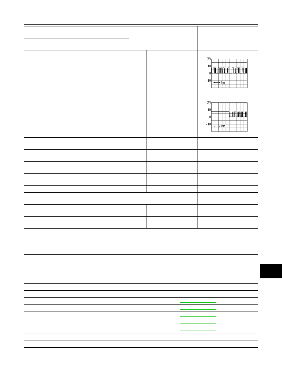
PHYSICAL VALUES

AWNIA1727ZZ

Terminal

(Wire color)

Description

Condition

Reference value

(Approx.)

+

–

Signal name

Input/

Output

1

(B)

Ground Ground

—

Ignition 

switch 

ON 

—

0V

2

(L)

Ground Inverter VCC

Input

Ignition 

switch 

ACC

—

9V

3

(V)

Ground Signal VCC

Input

Ignition 

switch 

ACC

—

9V

4

(W)

Ground Composite image ground

—

Ignition 

switch 

ON 

—

0V

5

—

Shield

—

—

—

—

6

(B)

Ground RGB signal (G: green)

Input

Ignition 

switch 

ON

Start Confirmation/Adjust-
ment mode, and then dis-
play color bar by selecting 
“Color Spectrum Bar” on 
Display Diagnosis screen.

7

—

Shield (RGB GND)

—

—

—

—

8

(G)

Ground

Horizontal synchronizing 
(HP) signal

Output

Ignition 

switch 

ON

—

JSNIA1030ZZ

SKIB3601E

AV-82

< ECU DIAGNOSIS INFORMATION >

[MID AUDIO WITHOUT BOSE]

DISPLAY UNIT

9

(W)

Ground RGB area (YS) signal

Input

Ignition 

switch 

ON

At RGB image is displayed.

5V

At DVD image is displayed.

11

(W)

Ground

Communication signal
(CONT

→DISP)

Input

Ignition 

switch 

ON

When adjusting display 
brightness.

13

(LG)

Ground Inverter ground

—

Ignition 

switch 

ON

—

0V

14

(B)

Ground Signal ground

—

Ignition 

switch 

ON

—

0V

15

(B)

Ground Composite image signal

Input

Ignition 

switch 

ON

At rear view camera image 
is displayed.

17

(R)

Ground RGB signal (R: red)

Input

Ignition 

switch 

ON

Start Confirmation/Adjust-
ment mode, and then dis-
play color bar by selecting 
“Color Spectrum Bar” on 
Display Diagnosis screen.

18

(W)

Ground RGB signal (B: blue)

Input

Ignition 

switch 

ON

Start Confirmation/Adjust-
ment mode, and then dis-
play color bar by selecting 
“Color Spectrum Bar” on 
Display Diagnosis screen.

Terminal

(Wire color)

Description

Condition

Reference value

(Approx.)

+

–

Signal name

Input/

Output

PKIB4948J

PKIB5039J

SKIB2251J

JSNIA1029ZZ

JSNIA1031ZZ


Content   ..  61  62  63  64   ..