Nissan Teana J32. Manual - part 865


  Index      Nissan     Nissan Teana J32 (2008 year) - Service and Repair Manual


Search            


Content   ..  863  864  865  866   ..


Nissan Teana J32. Manual - part 865


PCS-66

< COMPONENT DIAGNOSIS >

[POWER DISTRIBUTION SYSTEM]

PUSH-BUTTON IGNITION SWITCH POSITION INDICATOR

PUSH-BUTTON IGNITION SWITCH POSITION INDICATOR

Description

INFOID:0000000003805763

The switch that changes the power supply position.
BCM maintains the power supply position status.
BCM changes the power supply position with the operation of the push-button ignition switch.

Component Function Check

INFOID:0000000003805764

1.

CHECK FUNCTION

Check push-button ignition switch (“LOCK INDICATOR”, “ACC INDICATOR” and “IGNITION ON IND”) in
Active Test Mode with CONSULT-III.

Is the inspection result normal?

YES

>> INSPECTION END

NO

>> Refer to 

PCS-66, "Diagnosis Procedure"

.

Diagnosis Procedure

INFOID:0000000003805765

1.

CHECK PUSH-BUTTON IGNITION SWITCH INPUT SIGNAL

1.

Turn ignition switch OFF.

2.

Disconnect push-button ignition switch connector.

3.

Check voltage between push-button ignition switch harness connector and ground.

Is the inspection result normal?

YES

>> GO TO 2.

NO

>>

Check the following.

• 10A fuse [No.9, located in fuse block (J/B)]
• Harness for open or short between push-button ignition switch and fuse

2.

CHECK PUSH-BUTTON IGNITION SWITCH CIRCUIT

1.

Disconnect BCM connector.

2.

Check continuity between BCM harness connector and push-button ignition switch harness connector.

3.

Check continuity between BCM harness connector and ground.
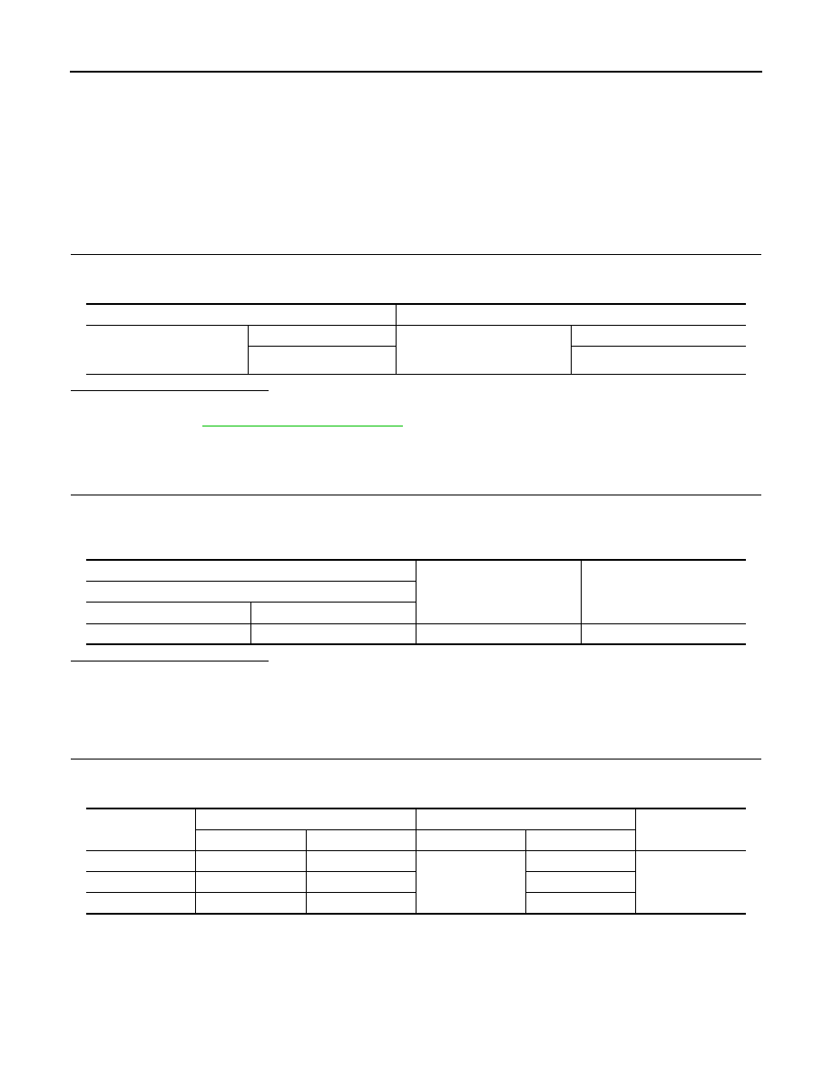
Test item

Description

LOCK INDICATOR
ACC INDICATOR
IGNITION ON IND

ON

Position indicator

 Illuminates

OFF

Does not illuminate

(+)

(–)

Voltage (V)

(Approx.)

Push-button ignition switch

Connector

Terminal

M101

8

Ground

Battery voltage

Indicator

BCM

 Push-button ignition switch

Continuity

Connector

Terminal

Connector

Terminal

LOCK

M123

134

M101

5

Existed

ACC

M119

15

6

ON

M122

93

7

PCS

PUSH-BUTTON IGNITION SWITCH POSITION INDICATOR

PCS-67

< COMPONENT DIAGNOSIS >

[POWER DISTRIBUTION SYSTEM]

C

D

E

F

G

H

I

J

K

L

B

A

O

P

N

Is the inspection result normal?

YES

>> GO TO 3.

NO

>> Repair or replace harness.

3.

CHECK PUSH-BUTTON IGNITION SWITCH

Refer to 

PCS-67, "Component Inspection"

.

Is the inspection result normal?

YES

>> GO TO 4.

NO

>> Replace push-button ignition switch. Refer to 

PCS-127, "Removal and Installation"

.

4.

CHECK INTERMITTENT INCIDENT

Refer to 

GI-35, "Intermittent Incident"

.

>> INSPECTION END

Component Inspection

INFOID:0000000003805766

1.

CHECK PUSH-BUTTON IGNITION SWITCH 

1.

Turn ignition switch OFF.

2.

Disconnect push-button ignition switch connector.

3.

Check continuity between push-button ignition switch terminals.

Is the inspection result normal?

YES

>> INSPECTION END

NO

>> Replace push-button ignition switch. Refer to 

PCS-127, "Removal and Installation"

.

Indicator

BCM

Ground

Continuity

Connector

Terminal

LOCK

M123

134

Not existed

ACC

M119

15

ON

M122

93

Terminal

Continuity

Push-button ignition switch

(+)

(-)

5

8

Not  existed

8

5

Existed

6

8

Not  existed

8

6

Existed

7

8

Not  existed

8

7

Existed

PCS-68

< COMPONENT DIAGNOSIS >

[POWER DISTRIBUTION SYSTEM]

POWER DISTRIBUTION SYSTEM

POWER DISTRIBUTION SYSTEM

Wiring Diagram - PDS (POWER DISTRIBUTION SYSTEM) -

INFOID:0000000003845532

JCMWM1686GB

PCS

POWER DISTRIBUTION SYSTEM

PCS-69

< COMPONENT DIAGNOSIS >

[POWER DISTRIBUTION SYSTEM]

C

D

E

F

G

H

I

J

K

L

B

A

O

P

N

JCMWM1687GB


Content   ..  863  864  865  866   ..