Nissan Teana J32. Manual - part 775


  Index      Nissan     Nissan Teana J32 (2008 year) - Service and Repair Manual


Search            


Content   ..  773  774  775  776   ..


Nissan Teana J32. Manual - part 775


LAN-30

< COMPONENT DIAGNOSIS >

[CAN]

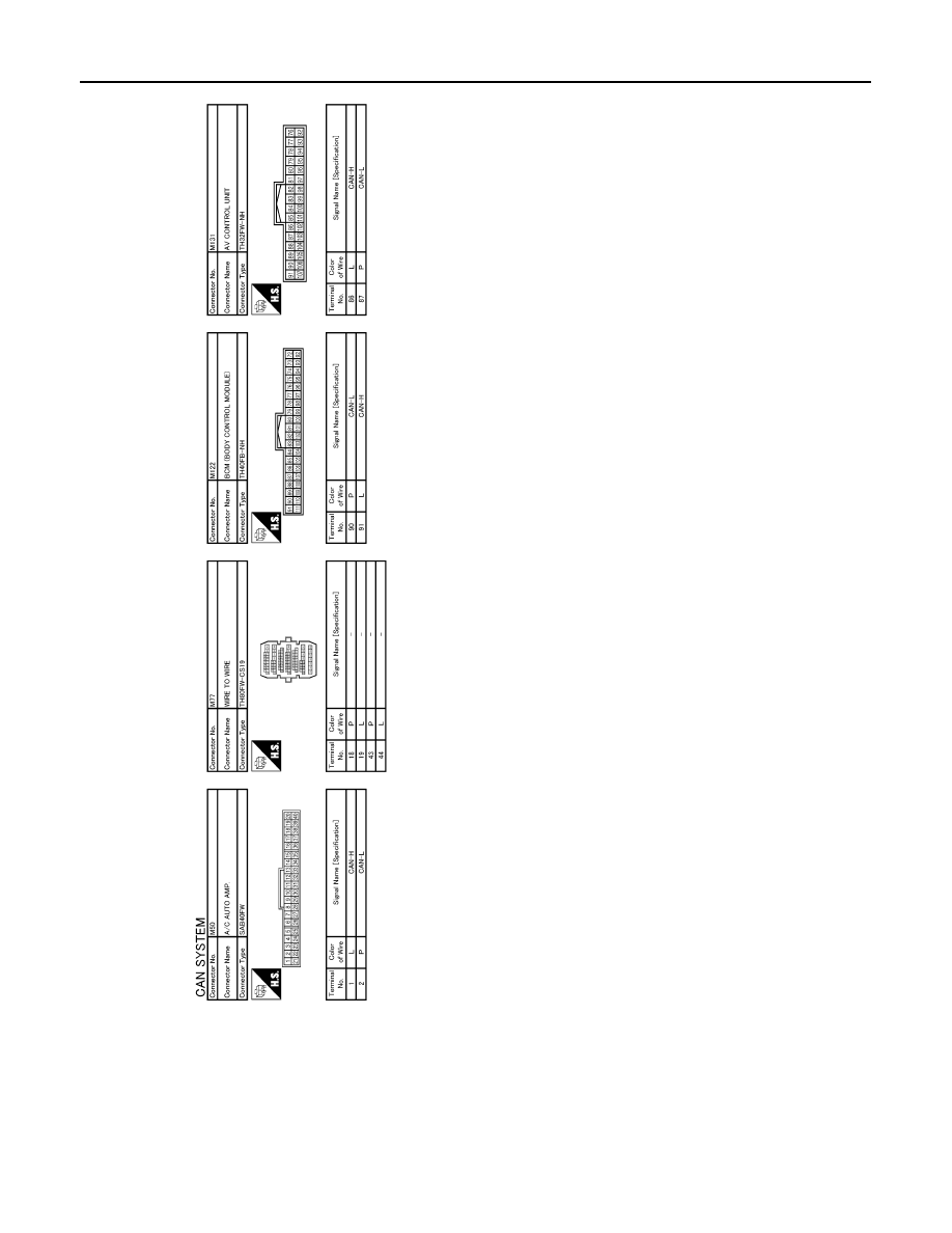
CAN COMMUNICATION SYSTEM

JCMWM1681GB

LAN

MALFUNCTION AREA CHART

LAN-31

< COMPONENT DIAGNOSIS >

[CAN]

C

D

E

F

G

H

I

J

K

L

B

A

O

P

N

MALFUNCTION AREA CHART

Main Line

INFOID:0000000003767688

Branch Line

INFOID:0000000003767689

Short Circuit

INFOID:0000000003767690

Malfunction Area

Reference

Main line between driver seat control unit and data link connector

LAN-32, "Diagnosis Procedure"

Main line between data link connector and BCM

LAN-33, "Diagnosis Procedure"

Main line between BCM and ABS actuator and electric unit (con-
trol unit)

LAN-34, "Diagnosis Procedure"

Malfunction Area

Reference

ECM branch line circuit 

LAN-35, "Diagnosis Procedure"

Driver seat control unit branch line circuit 

LAN-36, "Diagnosis Procedure"

Data link connector branch line circuit 

LAN-37, "Diagnosis Procedure"

AV control unit branch line circuit

LAN-38, "Diagnosis Procedure"

BCM branch line circuit 

LAN-39, "Diagnosis Procedure"

A/C auto amp. branch line circuit 

LAN-40, "Diagnosis Procedure"

Combination meter branch line circuit 

LAN-41, "Diagnosis Procedure"

Steering angle sensor branch line circuit 

LAN-42, "Diagnosis Procedure"

ABS actuator and electric unit (control unit) branch line circuit 

LAN-43, "Diagnosis Procedure"

TCM branch line circuit

LAN-44, "Diagnosis Procedure"

IPDM E/R branch line circuit 

LAN-45, "Diagnosis Procedure"

Malfunction Area

Reference

CAN communication circuit

LAN-46, "Diagnosis Procedure"

LAN-32

< COMPONENT DIAGNOSIS >

[CAN]

MAIN LINE BETWEEN ADP AND DLC CIRCUIT

MAIN LINE BETWEEN ADP AND DLC CIRCUIT

Diagnosis Procedure

INFOID:0000000003767691

1.

CHECK CONNECTOR

1.

Turn the ignition switch OFF.

2.

Disconnect the battery cable from the negative terminal.

3.

Check the following terminals and connectors for damage, bend and loose connection (connector side
and harness side).

-

Harness connector B11

-

Harness connector M77

Is the inspection result normal?

YES

>> GO TO 2.

NO

>> Repair the terminal and connector.

2.

CHECK HARNESS CONTINUITY (OPEN CIRCUIT)

1.

Disconnect the harness connectors B11 and M77.

2.

Check the continuity between the harness connector terminals.

Is the inspection result normal?

YES

>> GO TO 3.

NO

>> Repair the main line between the driver seat control unit and the harness connector B11.

3.

CHECK HARNESS CONTINUITY (OPEN CIRCUIT)

Check the continuity between the harness connector and the data link connector.

Is the inspection result normal?

YES (Present error)>>Check CAN system type decision again.
YES (Past error)>>Error was detected in the main line between the driver seat control unit and the data link

connector. 

NO

>> Repair the main line between the harness connector M77 and the data link connector.

Connector No.

Terminal No.

Continuity

B11

19

44

Existed

18

43

Harness connector

Data link connector

Continuity

Connector No.

Terminal No.

Connector No.

Terminal No.

M77

44

M4

6

Existed

43

14

Existed

LAN

MAIN LINE BETWEEN DLC AND BCM CIRCUIT

LAN-33

< COMPONENT DIAGNOSIS >

[CAN]

C

D

E

F

G

H

I

J

K

L

B

A

O

P

N

MAIN LINE BETWEEN DLC AND BCM CIRCUIT

Diagnosis Procedure

INFOID:0000000003767692

INSPECTION PROCEDURE

1.

CHECK HARNESS CONTINUITY (OPEN CIRCUIT)

1.

Turn the ignition switch OFF.

2.

Disconnect the battery cable from the negative terminal.

3.

Disconnect the following harness connectors.

-

ECM

-

BCM

4.

Check the continuity between the data link connector and the BCM harness connector.

Is the inspection result normal?

YES (Present error)>>Check CAN system type decision again.
YES (Past error)>>Error was detected in the main line between the data link connector and the BCM. 
NO

>> Repair the main line between the data link connector and the BCM.

Data link connector

BCM harness connector

Continuity

Connector No.

Terminal No.

Connector No.

Terminal No.

M4

6

M122

91

Existed

14

90

Existed


Content   ..  773  774  775  776   ..