Nissan Teana J32. Manual - part 666


  Index      Nissan     Nissan Teana J32 (2008 year) - Service and Repair Manual


Search            


Content   ..  664  665  666  667   ..


Nissan Teana J32. Manual - part 666


INTAKE DOOR CONTROL SYSTEM

HAC-33

< FUNCTION DIAGNOSIS >

[WITHOUT 7 INCH DISPLAY]

C

D

E

F

G

H

J

K

L

M

A

B

HAC

N

O

P

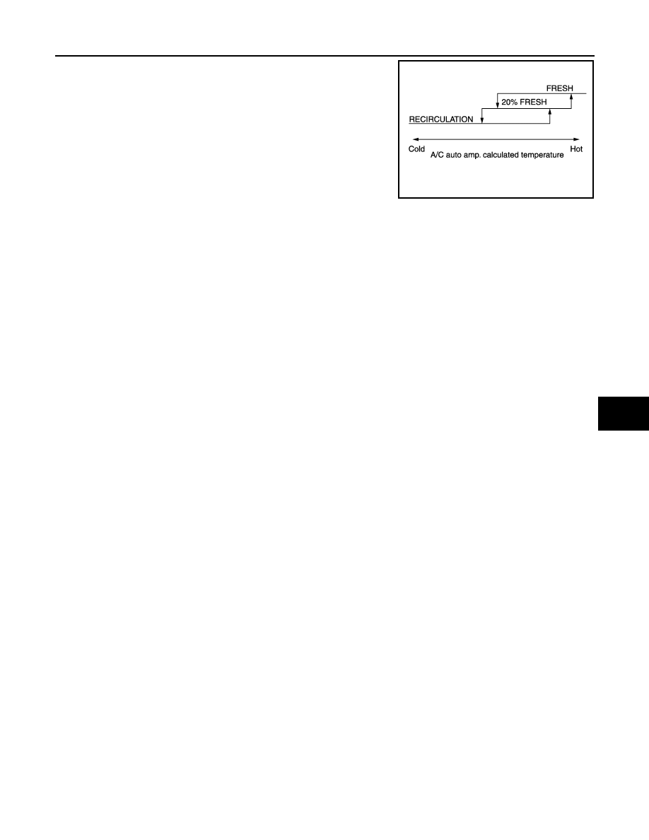
• Intake door position is basically set to the FRE when the FRE indi-

cator is ON or DEF switch is ON.

• Intake door position is basically set to the REC when the REC indi-

cator is ON.

• The intake door automatic control selects the FRE, the 20% FRE,

or the REC depending on the target air mix door opening angle,
based on in-vehicle temperature, ambient temperature, and sun-
load.

JPIIA0634GB

HAC-34

< FUNCTION DIAGNOSIS >

[WITHOUT 7 INCH DISPLAY]

BLOWER MOTOR CONTROL SYSTEM

BLOWER MOTOR CONTROL SYSTEM

System Diagram

INFOID:0000000003846315

System Description

INFOID:0000000003846316

Blower speed is automatically controlled by the temperature setting, ambient temperature, in-vehicle tempera-
ture, intake temperature, amount of sunload and air mix door position.
By pressing the AUTO switch, the blower motor starts to gradually increase air flow volume.
When engine coolant temperature is low, the blower motor operation is delayed to prevent cool air from flow-
ing.

SYSTEM OPERATION

System Operation

• For air flow, the manual selection (1-7) with the fan control dial has priority. 
• If the AUTO switch is pressed or if the DEF switch is pressed while in the OFF condition, it changes to the

automatic control by A/C auto amp. 

• When increasing the air flow, it changes the duty ratio of the blower motor drive signal to prevent the air flow

from suddenly increasing. 

• There are the following types of air flow control: starting air flow control, starting air flow control at low cool-

ant temperature, starting air flow control at high in-vehicle temperature, and air flow control at actuator oper-
ation in addition to manual control, normal automatic air flow control. 

Normal Automatic Air Flow Control

• When the target temperature is set by the temperature control switch of A/C control, the A/C auto amp. per-

forms the calculation and decides the target according to the signal from each sensor. 

• The A/C auto amp. changes the duty ratio of blower motor drive signal and controls the air flow continuously

so that the air flow becomes the target air flow. 

• The minimum air flow will change according to the sunload when the air discharge outlet is VENT or B/L. 

Fan Speed Control Specification

JPIIA0502GB

JPIIA0635GB

BLOWER MOTOR CONTROL SYSTEM

HAC-35

< FUNCTION DIAGNOSIS >

[WITHOUT 7 INCH DISPLAY]

C

D

E

F

G

H

J

K

L

M

A

B

HAC

N

O

P

Starting Air Flow Control

• When starting the automatic control of air flow, the system gradually increases the duty ratio of the blower

motor drive signal to prevent too much air from blowing. 

• The time period from when the air flow changes from LO to HI is approximately 8 seconds. 
• It becomes the starting air flow control at low coolant temperature according to the calculation result of the A/

C auto amp. and engine coolant temperature [approximately 56

°

C (133

°

F) or less] during the automatic air

flow control. 

• Do not perform the starting air flow control when the air discharge outlet is set to DEF. 

Starting Fan Speed Control

Start up from COLD SOAK Condition (Automatic mode)
In cold start up condition where the engine coolant temperature is below 56

°

C (133

°

F), the blower does not

operate for a short period of time (up to 150 seconds). The exact start delay time varies depending on the
ambient temperature and engine coolant temperature.
In the most extreme case (very low ambient temperature) the blower start delay is 150 seconds as described
above. After this delay, the blower will operate at low speed until the engine coolant temperature rises above
56

°

C (133

°

F), and then the blower speed increases to the objective speed.

Start up from usual or HOT SOAK Condition (Automatic mode)
The blower will begin operation momentarily after the AUTO switch is pressed. The blower speed rises gradu-
ally to the objective speed over a time period of 3 seconds or less (actual time depends on the objective
blower speed).

HAC-36

< FUNCTION DIAGNOSIS >

[WITHOUT 7 INCH DISPLAY]

MAGNET CLUTCH CONTROL SYSTEM

MAGNET CLUTCH CONTROL SYSTEM

System Diagram

INFOID:0000000003846317

System Description

INFOID:0000000003846318

The A/C auto amp. controls compressor operation by ambient temperature, intake air temperature and signal
from ECM.

SYSTEM OPERATION

When the A/C switch, the AUTO switch, or the DEF switch is pressed, A/C auto amp. transmit the A/C switch
signal and blower fan motor switch signal to the ECM, via CAN communication.
ECM judges whether compressor can be turned ON, based on each sensor status (refrigerant-pressure sen-
sor signal, throttle angle, etc.). If the ECM judges that the compressor can be turned ON, it sends A/C com-
pressor request signal to the IPDM E/R, via CAN communication.
Upon receipt of A/C compressor request signal from the ECM, the IPDM E/R turns the A/C relay ON to oper-
ate the compressor.
When sending A/C compressor request signal to the IPDM E/R via CAN communication line, the ECM simul-
taneously sends A/C compressor feedback signal to A/C auto amp. via CAN communication line.
The ECM sends A/C compressor feedback signal to A/C auto amp., then, uses input A/C compressor feed-
back signal to control air inlet.

Compressor Protection Control

The ECM makes the A/C relay turn OFF and stops the compressor when pressure on the high-pressure side
detected by the refrigerant pressure sensor is over approximately 3,119 kPa (31.19bar, 31.8 kg/cm

2

, 452 psi),

or below approximately 118 kPa (1.18bar, 1.2 kg/cm

2

, 17 psi).

Low Temperature Protection Control

Turn the A/C relay to OFF and stop the compressor by the signal from the A/C auto amp according to the
evaporator passing air temperature detected by the intake sensor and the ambient temperature detected by
the ambient sensor. 

JPIIA0504GB


Content   ..  664  665  666  667   ..