Nissan Teana J32. Manual - part 634


  Index      Nissan     Nissan Teana J32 (2008 year) - Service and Repair Manual


Search            


Content   ..  632  633  634  635   ..


Nissan Teana J32. Manual - part 634


GI-40

< BASIC INSPECTION >

SERVICE INFORMATION FOR ELECTRICAL INCIDENT

• For detailed ground distribution information, refer to “Ground Distribution” in PG section.
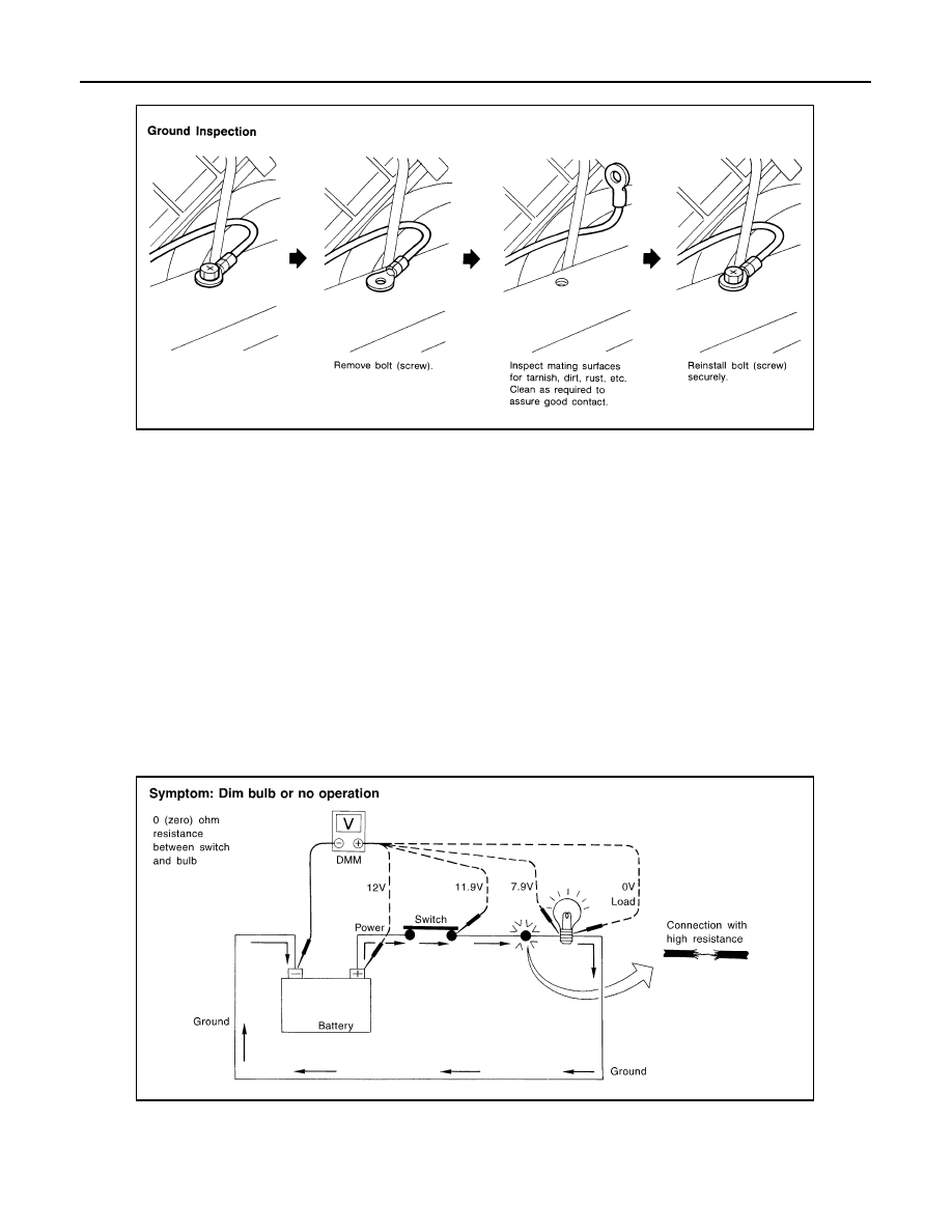
VOLTAGE DROP TESTS 

• Voltage drop tests are often used to find components or circuits which have excessive resistance. A voltage

drop in a circuit is caused by a resistance when the circuit is in operation.

• Check the wire in the illustration. When measuring resistance with DMM, contact by a single strand of wire

will give reading of 0 ohms. This would indicate a good circuit. When the circuit operates, this single strand
of wire is not able to carry the current. The single strand will have a high resistance to the current. This will
be picked up as a slight voltage drop. 

• Unwanted resistance can be caused by many situations as follows:
- Undersized wiring (single strand example)
- Corrosion on switch contacts
- Loose wire connections or splices.
• If repairs are needed always use wire that is of the same or larger gauge.

Measuring Voltage Drop — Accumulated Method

• Connect the DMM across the connector or part of the circuit you want to check. The positive lead of the

DMM should be closer to power and the negative lead closer to ground.

• Operate the circuit.
• The DMM will indicate how many volts are being used to “push” current through that part of the circuit.
Note in the illustration that there is an excessive 4.1 volt drop between the battery and the bulb.

Measuring Voltage Drop — Steb-by-Step

• The step-by-step method is most useful for isolating excessive drops in low voltage systems (such as those

in “Computer Controlled Systems”).

• Circuits in the “Computer Controlled System” operate on very low amperage.

SGI853

SGI974

SERVICE INFORMATION FOR ELECTRICAL INCIDENT

GI-41

< BASIC INSPECTION >

C

D

E

F

G

H

I

J

K

L

M

B

GI

N

O

P

• The (Computer Controlled) system operations can be adversely affected by any variation in resistance in the

system. Such resistance variation may be caused by poor connection, improper installation, improper wire
gauge or corrosion.

• The step by step voltage drop test can identify a component or wire with too much resistance.

CONTROL UNIT CIRCUIT TEST 

System Description
• When the switch is ON, the control unit lights up the lamp.

CASE 1

INPUT-OUTPUT VOLTAGE CHART

• The voltage value is based on the body ground.

• *: If high resistance exists in the switch side circuit (caused by a single strand), terminal 1 does not detect battery voltage. Control unit

does not detect the switch is ON even if the switch does not turn ON. Therefore, the control unit does not supply power to light up the
lamp.

SAIA0258E

Terminal No.

Description

Condition

Value (Approx.)

In case of high resistance such as single 
strand (V) *

+

Signal name

Input/

Output

1

Body 
ground

Switch

Input

Switch ON

Battery voltage

Lower than battery voltage Approx. 8 (Ex-
ample)

Switch OFF

0 V

Approx. 0

2

Body 
ground

Lamp

Output

Switch ON

Battery voltage

Approx. 0 (Inoperative lamp)

Switch OFF

0 V

Approx. 0

MGI034A

GI-42

< BASIC INSPECTION >

SERVICE INFORMATION FOR ELECTRICAL INCIDENT

CASE 2

INPUT-OUTPUT VOLTAGE CHART

• The voltage value is based on the body ground.

• *: If high resistance exists in the switch side circuit (caused by a single strand), terminal 2 does not detect approx. 0V. Control unit

does not detect the switch is ON even if the switch does not turn ON. Therefore, the control unit does not control ground to light up the
lamp.

Terminal No.

Description

Condition

Value (Approx.)

In case of high resistance such as single 
strand (V) *

+

Signal name

Input/

Output

1

Body 
ground

Lamp

Output

Switch ON

0V

Battery voltage (Inoperative lamp)

Switch OFF

Battery voltage

Battery voltage

2

Body 
ground

Switch

Input

Switch ON

0 V

Higher than 0 Approx. 4 (Example)

Switch OFF

5 V

Approx. 5

MGI035A

CONSULT-III/GST CHECKING SYSTEM

GI-43

< BASIC INSPECTION >

C

D

E

F

G

H

I

J

K

L

M

B

GI

N

O

P

CONSULT-III/GST CHECKING SYSTEM

Description

INFOID:0000000003852797

• When CONSULT-III/GST is connected with a data link connector

(A) equipped on the vehicle side, it will communicate with the con-
trol unit equipped in the vehicle and then enable various kinds of
diagnostic tests.

• Refer to “CONSULT-III Software Operation Manual” for more infor-

mation.

CONSULT-III Function and System Application*1

INFOID:0000000003852798

x: Applicable

*1: If GST application is equipped, functions in accordance with SAE J1979 and ISO 15031-5 can be used.

CONSULT-III/GST Data Link Connector (DLC) Circuit

INFOID:0000000003852799

INSPECTION PROCEDURE

If the CONSULT-III/GST cannot diagnose the system properly, check the following items.

1

: Instrument driver lower panel

JPAIA0313GB

Diagnostic test mode

Function

ENGINE

TRANSMISSION

AIR BAG

METER/M

&

A

BCM

AUT

O

 DRIV

E

 POS.

ABS

ABS (Includi

ng 

VDC)

IP

DM E/

R

HEAD LAMP LE

VELI

Z

ER

MUL

T

I A

V

HV

AC

Work Support

This mode enables a technician to adjust some devices 
faster and more accurately.

x

x

-

-

x

x

-

x

-

x

-

x

Self-Diagnostic Results

Retrieve DTC from ECU and display diagnostic items.

x

x

x

x

x

x

x

x

x

x

x

x

Data Monitor

Monitor the input/output signal of the control unit in real 
time.

x

x

-

x

x

x

x

x

x

x

x

x

CAN Diagnosis

This mode displays a network diagnosis result about 
CAN by a diagram.

x

x

-

x

x

x

x

x

x

-

x

x

CAN Diagnosis Support 
Monitor

It monitors the status of CAN communication.

x

x

-

x

x

x

x

x

x

-

x

-

Active Test

Send the drive signal from CONSULT-III to the actua-
tor. The operation check can be performed.

x

-

-

-

x

x

x

x

x

x

-

x

DTC & SRT confirma-
tion

The status of system monitoring tests and the self-diag-
nosis status/result can be confirmed.

x

-

-

-

-

-

-

-

-

-

-

-

ECU Identification

Display the ECU identification number (part number 
etc.) of the selected system.

x

x

-

-

x

x

x

x

x

x

x

x

Function Test

This mode can show results of self-diagnosis of ECU 
with either "OK" or "NG". For engine, more practical 
tests regarding sensors/switches and/or actuators are 
available.

x

x

x

-

-

-

x

x

-

-

-

-

Configuration

Function to READ/WRITE vehicle configuration

-

-

-

-

x

-

-

-

-

x

-

-

Special Function

Other results or histories, etc. that are recorded in ECU 
are displayed.

-

x

x

x

-

-

-

-

-

-

-

-


Content   ..  632  633  634  635   ..