Nissan Teana J32. Manual - part 611


  Index      Nissan     Nissan Teana J32 (2008 year) - Service and Repair Manual


Search            


Content   ..  609  610  611  612   ..


Nissan Teana J32. Manual - part 611


FRONT DRIVE SHAFT BOOT

FAX-15

< ON-VEHICLE REPAIR >

C

E

F

G

H

I

J

K

L

M

A

B

FAX

N

O

P

20. Install wheel sensor and sensor harness to steering knuckle. Refer to 

BRC-57, "FRONT WHEEL SEN-

SOR : Exploded View"

 (without VDC), 

BRC-151, "FRONT WHEEL SENSOR : Exploded View"

 (with

VDC).

TRANSAXLE SIDE

TRANSAXLE SIDE : Removal and Installation

INFOID:0000000003811081

Remove boot after removing drive shaft.
• Remove: refer to 

FAX-18, "LEFT SIDE : Removal and Installation"

 (left side), 

FAX-19, "RIGHT SIDE :

Removal and Installation"

 (right side).

• Disassembly: refer to 

FAX-22, "TRANSAXLE SIDE : Disassembly and Assembly"

.

Inspection

INFOID:0000000003811082

INSPECTION AFTER REMOVAL

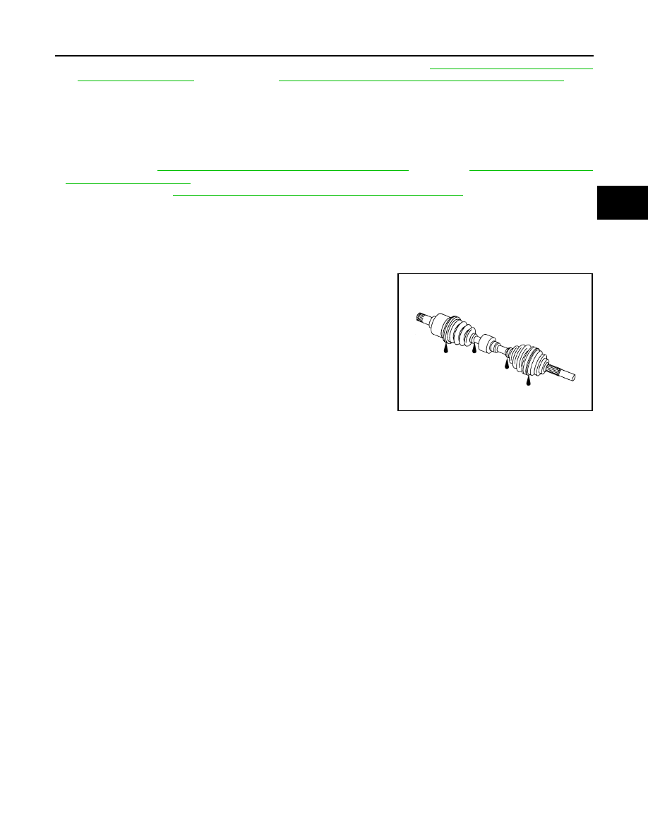
• Move joint up/down, left/right, and in the axial directions. Check for motion that is not smooth and for signifi-

cant looseness.

• Check boot for cracks, damage, and leakage of grease.
• Disassemble drive shaft and exchange malfunctioning part if there

is a non-standard condition.

SDIA1190J

FAX-16

< ON-VEHICLE REPAIR >

FRONT DRIVE SHAFT

FRONT DRIVE SHAFT

Exploded View

INFOID:0000000003812421

LEFT SIDE

VQ25DE

VQ35DE

JPDIF0193ZZ

1.

Circular clip

2.

Dust shield

3.

Housing

4.

Snap ring

5.

Spider assembly

6.

Boot band

7.

Boot

8.

Shaft

9.

Damper band

10. Dynamic damper

11.

Circular clip

12. Joint sub-assembly

: Wheel side

: Fill NISSAN Genuine grease or equivalent.

Refer to 

GI-4, "Components"

 for symbols not described on the above.

JPDIF0141ZZ

1.

Circular clip

2.

Dust shield

3.

Housing assembly

4.

Boot band

5.

Boot

6.

Circular clip

7.

Joint sub-assembly

: Wheel side

FRONT DRIVE SHAFT

FAX-17

< ON-VEHICLE REPAIR >

C

E

F

G

H

I

J

K

L

M

A

B

FAX

N

O

P

RIGHT SIDE

VQ25DE

VQ35DE

: Fill NISSAN Genuine grease or equivalent.

Refer to 

GI-4, "Components"

 for symbols not described on the above.

JPDIF0184GB

1.

Joint sub-assembly

2.

Circular clip

3.

Boot band

4.

Boot

5.

Shaft

6.

Damper band

7.

Dynamic damper

8.

Spider assembly

9.

Snap ring

10. Housing

11.

Dust shield

12. Support bearing

13. Snap ring

14. Dust shield

15. Plate

16. Support bearing bracket

: Wheel side

: Fill NISSAN Genuine grease or equivalent.

Refer to 

GI-4, "Components"

 for symbols not described on the above.

JPDIF0182GB

1.

Joint sub-assembly

2.

Circular clip

3.

Boot band

4.

Boot

5.

Damper band

6.

Dynamic damper

7.

Housing assembly

8.

Dust shield

9.

Snap ring

10. Support bearing

11.

Baring housing

12. Support bearing bracket

FAX-18

< ON-VEHICLE REPAIR >

FRONT DRIVE SHAFT

LEFT SIDE

LEFT SIDE : Removal and Installation

INFOID:0000000003811084

REMOVAL

1.

Remove tires.

2.

Remove wheel sensor and sensor harness. Refer to 

BRC-57, "FRONT WHEEL SENSOR : Exploded

View"

 (without VDC), 

BRC-151, "FRONT WHEEL SENSOR : Exploded View"

 (with VDC).

3.

Remove lock plate of brake hose from strut assembly. Refer to 

BR-19, "FRONT : Exploded View"

.

4.

Remove caliper assembly. Hang caliper assembly not to interfere with work. Refer to 

BR-34, "BRAKE

CALIPER ASSEMBLY : Exploded View"

.

5.

Remove disc rotor. Refer to 

BR-35, "BRAKE CALIPER ASSEMBLY : Removal and Installation"

.

6.

Remove cotter pin, and then loosen wheel hub lock nut. Refer to 

FAX-8, "Exploded View"

.

7.

Patch wheel hub lock nut with a piece of wood. Hammer the
wood to disengage drive shaft from wheel hub and bearing
assembly.

CAUTION:

• Never place drive shaft joint at an extreme angle. Also be

careful not to overextend slide joint.

• Never allow drive shaft to hang down without support for

joint sub-assembly and the other parts.

NOTE:
Use suitable puller, if wheel hub and bearing assembly and drive
shaft cannot be separated even after performing the above pro-
cedure.

8.

Remove wheel hub lock nut.

9.

Remove steering knuckle from strut assembly. Refer to 

FSU-9, "Exploded View"

.

10. Remove drive shaft from wheel hub and bearing assembly.

11. Remove drive shaft from transaxle assembly.

• Use the drive shaft attachment (A) (SST: KV40107500) and a

sliding hammer (B) while inserting tip of the drive shaft attach-
ment between housing assembly and transaxle assembly.

CAUTION:

Never place drive shaft joint at an extreme angle when
removing drive shaft. Also be careful not to overextend
slide joint.

INSTALLATION

Note the following, and install in the reverse order of removal.
• Always replace differential side oil seal with new one when installing drive shaft. Refer to 

TM-162, "Exploded

View"

 (CVT: RE0F09B), 

TM-325, "Exploded View"

 (CVT: RE0F10A).

: Wheel side

: Fill NISSAN Genuine grease or equivalent.

Refer to 

GI-4, "Components"

 for symbols not described on the above.

JPDIG0070ZZ

JPDIF0004ZZ


Content   ..  609  610  611  612   ..