Nissan Teana J32. Manual - part 447


  Index      Nissan     Nissan Teana J32 (2008 year) - Service and Repair Manual


Search            


Content   ..  445  446  447  448   ..


Nissan Teana J32. Manual - part 447


EC-326

< COMPONENT DIAGNOSIS >

[VQ25DE, VQ35DE]

COOLING FAN

3.

Also check harness for short to ground and short to power.

Is the inspection result normal?

YES

>> GO TO 8.

NO

>> GO TO 7.

7.

DETECT MALFUNCTIONING PART

Check the following.
• Harness connector E70, E305
• Harness for open or short between cooling fan motor-1 and cooling fan relay-2
• Harness for open or short between cooling fan motor-1 and cooling fan relay-3
• Harness for open or short between cooling fan motor-2 and cooling fan relay-2
• Harness for open or short between cooling fan motor-2 and cooling fan relay-3

>> Repair open circuit, short to ground or short to power in harness or connectors.

8.

CHECK COOLING FAN MOTOR CIRCUIT-II

1.

Check the continuity between IPDM E/R harness connector and cooling fan motor-1, -2 harness connec-
tor.

2.

Also check harness for short to ground and short to power.

Is the inspection result normal?

YES

>> GO TO 10.

NO

>> GO TO 9.

9.

DETECT MALFUNCTIONING PART

Check the following.
• Harness connector E70, E305
• Harness for open or short between cooling fan motor-1 and IPDM E/R
• Harness for open or short between cooling fan motor-2 and IPDM E/R

>> Repair open circuit, short to ground or short to power in harness or connectors.

10.

CHECK COOLING FAN MOTOR CIRCUIT-III
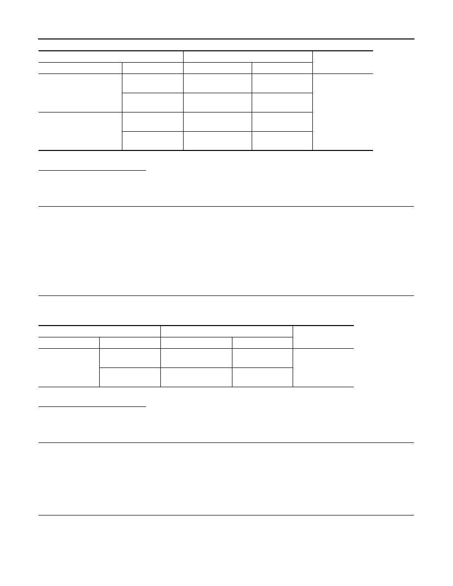
1.

Check the continuity between cooling fan relay-2, -3 harness connectors and ground.

Cooling fan relay

Cooling fan motor

Continuity

Connector

Terminal

Connector

Terminal

E57

(cooling fan relay-2)

3

E302

(Cooling fan motor-2)

2

Existed

7

E301

(Cooling fan motor-1)

3

E59

(cooling fan relay-3)

3

E302

(Cooling fan motor-2)

1

7

E301

(Cooling fan motor-1)

4

IPDM E/R

Cooling fan motor

Continuity

Connector

Terminal

Connector

Terminal

E10

35

E301

(Cooling fan motor-1)

4

Existed

38

E302

(Cooling fan motor-2)

1

COOLING FAN

EC-327

< COMPONENT DIAGNOSIS >

[VQ25DE, VQ35DE]

C

D

E

F

G

H

I

J

K

L

M

A

EC

N

P

O

2.

Also check harness for short to ground and short to power.

Is the inspection result normal?

YES

>> GO TO 11.

NO

>> Repair open circuit, short to ground or short to power in harness or connectors.

11.

CHECK COOLING FAN MOTOR CIRCUIT-IV

1.

Check the continuity between cooling fan motor-2 harness connector and ground.

2.

Also check harness for short to ground and short to power.

Is the inspection result normal?

YES

>> GO TO 12.

NO

>> Repair open circuit, short to ground or short to power in harness or connectors.

12.

CHECK COOLING FAN RELAYS-2 AND -3

Refer to 

EC-328, "Component Inspection (Cooling Fan Relay)"

.

Is the inspection result normal?

YES

>> GO TO 13.

NO

>> Replace malfunctioning cooling fan relay.

13.

CHECK COOLING FAN MOTORS-1 AND -2

Refer to 

EC-327, "Component Inspection (Cooling Fan Motor)"

.

Is the inspection result normal?

YES

>> GO TO 14.

NO

>> Replace malfunctioning cooling fan motor.

14.

CHECK INTERMITTENT INCIDENT

Perfor

GI-35, "Intermittent Incident"

.

Is the inspection result normal?

YES

>> Replace IPDM E/R.

NO

>> Repair or replace harness connectors.

Component Inspection (Cooling Fan Motor)

INFOID:0000000003856830

1.

CHECK COOLING FAN MOTOR

1.

Turn ignition switch OFF.

2.

Disconnect cooling fan motor harness connector.

3.

Supply cooling fan motor terminals with battery voltage and check operation.

Cooling fan motor

Ground

Continuity

Connector

Terminal

E57

(cooling fan relay-2)

6

Ground

Existed

E59

(cooling fan relay-3)

6

Cooling fan motor-2

Ground

Continuity

Connector

Terminal

E302

3

Ground

Existed

4

EC-328

< COMPONENT DIAGNOSIS >

[VQ25DE, VQ35DE]

COOLING FAN

Check that cooling fan speed of condition B is higher than that of A.

Is the inspection result normal?

YES

>> INSPECTION END

NO

>> Replace cooling fan motor.

Component Inspection (Cooling Fan Relay)

INFOID:0000000003856831

1.

CHECK COOLING FAN RELAY

1.

Disconnect cooling fan relays -2, -3 harness connectors.

2.

Check continuity between cooling fan relay -2, -3 terminals
under the following conditions.

Is the inspection result normal?

YES

>> INSPECTION END

NO

>> Replace cooling fan relay.

Condition

Terminals

(+)

(

)

Cooling fan motor

A

1

3 and 4

2

3 and 4

1 and 2

3

1 and 2

4

B

1, 2

3, 4

Terminals

Conditions

Continuity

3 and 5
6 and 7

12 V direct current supply between terminals 1 and 2

Existed

No current supply

Not existed

SEF745U

ELECTRICAL LOAD SIGNAL

EC-329

< COMPONENT DIAGNOSIS >

[VQ25DE, VQ35DE]

C

D

E

F

G

H

I

J

K

L

M

A

EC

N

P

O

ELECTRICAL LOAD SIGNAL

Description

INFOID:0000000003856832

The electrical load signal (Headlamp switch signal, rear window defogger switch signal, etc.) is transferred
through the CAN communication line from BCM to ECM via IPDM E/R.

Component Function Check

INFOID:0000000003856833

1.

CHECK REAR WINDOW DEFOGGER SWITCH FUNCTION

1.

Turn ignition switch ON.

2.

Connect CONSULT-III and select “DATA MONITOR” mode.

3.

Select “LOAD SIGNAL” and check indication under the following conditions.

Is the inspection result normal?

YES

>> GO TO 2.

NO

>> Go to 

EC-329, "Diagnosis Procedure"

.

2.

CHECK LIGHTING SWITCH FUNCTION

Check “LOAD SIGNAL” indication under the following conditions.

Is the inspection result normal?

YES

>> GO TO 3.

NO

>> Go to 

EC-329, "Diagnosis Procedure"

.

3.

CHECK HEATER FAN CONTROL SWITCH FUNCTION

Select “HEATER FAN SW” and check indication under the following conditions.

Is the inspection result normal?

YES

>> INSPECTION END

NO

>> Go to 

EC-329, "Diagnosis Procedure"

.

Diagnosis Procedure

INFOID:0000000003856834

1.

INSPECTION START

Confirm the malfunctioning circuit (rear window defogger, headlamp or heater fan). Refer to 

EC-329, "Compo-

nent Function Check"

.

Which circuit is related to the incident?

Rear window defogger>>GO TO 2.
Headlamp>>GO TO 3.
Heater fan>>GO TO 4.

2.

CHECK REAR WINDOW DEFOGGER SYSTEM

Refer to 

DEF-3, "Work Flow"

.

Monitor item

Condition

Indication

LOAD SIGNAL

Rear window defogger switch

ON

ON

OFF

OFF

Monitor item

Condition

Indication

LOAD SIGNAL

Lighting switch

ON at 2nd position

ON

OFF

OFF

Monitor item

Condition

Indication

HEATER FAN SW

Heater fan control switch

ON

ON

OFF

OFF


Content   ..  445  446  447  448   ..