Nissan Teana J32. Manual - part 384
EC-74
< FUNCTION DIAGNOSIS >
[VQ25DE, VQ35DE]
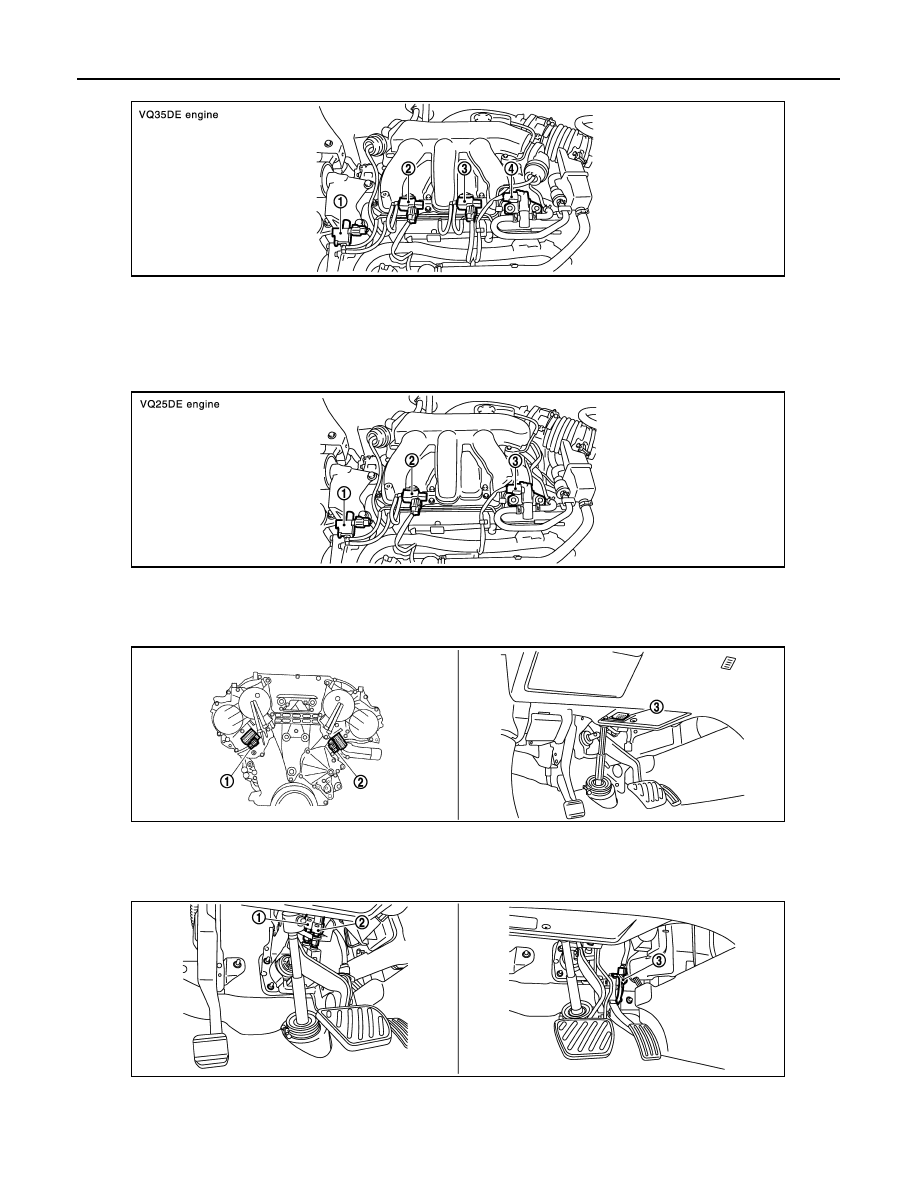
ELECTRONIC CONTROLLED ENGINE MOUNT
1.
Electronic controlled engine mount
control solenoid valve
2.
VIAS control solenoid valve 1
3.
VIAS control solenoid valve 2
4.
EVAP canister purge volume control
solenoid valve
1.
Electronic controlled engine mount
control solenoid valve
2.
VIAS control solenoid valve
3.
EVAP canister purge volume control
solenoid valve
1.
Intake valve timing control solenoid
valve (bank 1)
2.
Intake valve timing control solenoid
valve (bank 2)
3.
Data link connector
1.
Stop lamp switch
2.
ASCD brake switch
3.
Accelerator pedal position sensor
JMBIA1381GB
JMBIA1382GB
JMBIA1383ZZ
JMBIA1384ZZ