Nissan Teana J32. Manual - part 321


  Index      Nissan     Nissan Teana J32 (2008 year) - Service and Repair Manual


Search            


Content   ..  319  320  321  322   ..


Nissan Teana J32. Manual - part 321


REMOTE KEYLESS ENTRY RECEIVER

DLK-67

< COMPONENT DIAGNOSIS >

[WITH INTELLIGENT KEY SYSTEM]

C

D

E

F

G

H

I

J

L

M

A

B

DLK

N

O

P

REMOTE KEYLESS ENTRY RECEIVER

Description

INFOID:0000000003794867

Receives Intelligent Key operation and transmits to BCM.

Component Function Check

INFOID:0000000003794868

1.

CHECK FUNCTION

With CONSULT-III

Check remote keyless entry receiver (“RKE OPE COUN1”) in Data Monitor mode with CONSULT-III.

Is the inspection result normal?

YES

>> Remote keyless entry receiver is OK.

NO

>> Refer to 

DLK-67, "Diagnosis Procedure"

.

Diagnosis Procedure

INFOID:0000000003794869

1.

CHECK REMOTE KEYLESS ENTRY RECEIVER OUTPUT SIGNAL

1.

Turn ignition switch OFF.

2.

Check signal between remote keyless entry receiver harness connector and ground with oscilloscope.

Is the inspection result normal?

YES

>> GO TO 2.

NO

>> GO TO 3.

2.

CHECK REMOTE KEYLESS ENTRY RECEIVER CIRCUIT 1

1.

Disconnect BCM connector and remote keyless entry receiver connector.

2.

Check continuity between BCM harness connector and remote keyless entry receiver harness connector.

3.

Check continuity between BCM harness connector and ground.

Monitor item

Condition

RKE OPE COUN1

Checks whether value changes when operating Intelligent Key.
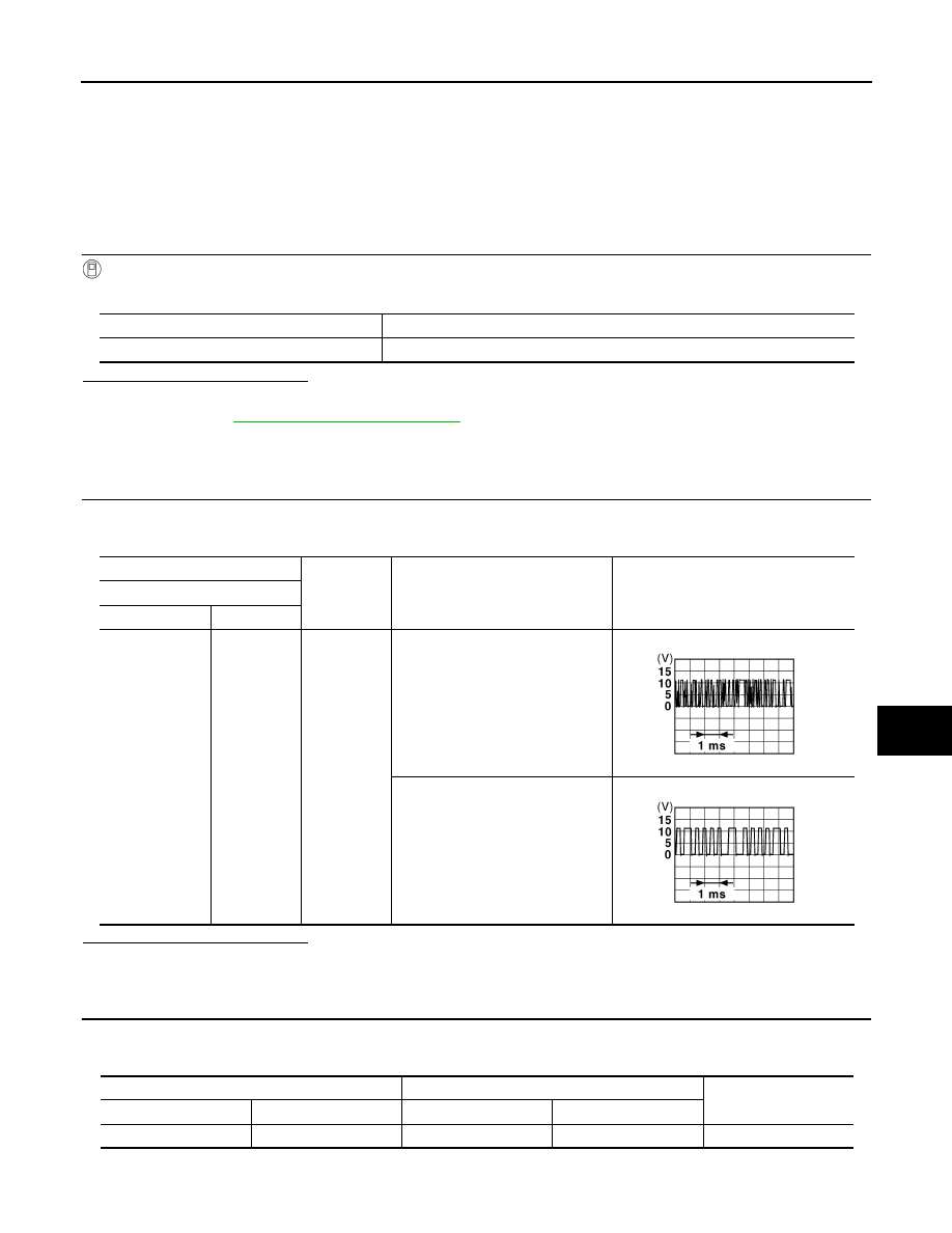
(+)

(–)

Condition

Signal

(Reference value)

Remote keyless entry receiver

Connector

Terminal

M78

2

Ground

Waiting

(All doors closed)

When signal is received

(All doors closed)

JMKIA0064GB

JMKIA0065GB

BCM

Remote keyless entry receiver

Continuity 

Connector

Terminal

Connector

Terminal

M122

83

M78

2

Existed

DLK-68

< COMPONENT DIAGNOSIS >

[WITH INTELLIGENT KEY SYSTEM]

REMOTE KEYLESS ENTRY RECEIVER

Is the inspection result normal?

YES

>> INSPECTION END.

NO

>> Repair or replace harness.

3.

CHECK REMOTE KEYLESS ENTRY RECEIVER POWER SUPPLY 

Check signal between remote keyless entry receiver harness connector and ground with oscilloscope.

Is the inspection result normal?

YES

>> GO TO 5.

NO

>> GO TO 4.

4.

CHECK REMOTE KEYLESS ENTRY RECEIVER CIRCUIT 2

1.

Disconnect BCM connector and remote keyless entry receiver.

2.

Check continuity between BCM harness connector and remote keyless entry receiver harness connector.

3.

Check continuity between BCM harness connector and ground.

Is the inspection result normal?

YES

>> Replace BCM. Refer to 

BCS-78, "Removal and Installation"

.

NO

>> Repair or replace harness.

5.

CHECK REMOTE KEYLESS ENTRY RECEIVER CIRCUIT 1

1.

Disconnect BCM connector and remote keyless entry receiver.

2.

Check continuity between BCM connector and remote keyless entry receiver connector.

3.

Check continuity between BCM harness connector and ground.

BCM

Ground

Continuity 

Connector

Terminal

M122

83

Not existed

(+)

(–)

Signal

(Reference value)

Remote keyless entry receiver

Connector

Terminal

M78

4

Ground

JMKIA0064GB

BCM

Remote keyless entry receiver

Continuity 

Connector

Terminal

Connector

Terminal

M122

103

M78

4

Existed

BCM

Ground

Continuity 

Connector

Terminal

M122

103

Not existed

BCM

Remote keyless entry receiver

Continuity 

Connector

Terminal

Connector

Terminal

M123

137

M78

1

Existed

REMOTE KEYLESS ENTRY RECEIVER

DLK-69

< COMPONENT DIAGNOSIS >

[WITH INTELLIGENT KEY SYSTEM]

C

D

E

F

G

H

I

J

L

M

A

B

DLK

N

O

P

Is the inspection result normal?

YES

>> GO TO 6.

NO

>> Repair or replace harness.

6.

CHECK REMOTE KEYLESS ENTRY RECEIVER GROUND CIRCUIT 2

1.

Connect remote keyless entry receiver connector.

2.

Check continuity between remote keyless entry receiver harness connector and ground.

Is the inspection result normal?

YES

>> Replace remote keyless entry receiver. Refer to 

DLK-244, "Removal and Installation"

.

NO

>> Replace BCM. Refer to 

BCS-78, "Removal and Installation"

BCM

Ground

Continuity 

Connector

Terminal

M122

137

Not existed

Remote keyless entry receiver

Ground

Continuity

Connector

Terminal

M78

1

Existed

DLK-70

< COMPONENT DIAGNOSIS >

[WITH INTELLIGENT KEY SYSTEM]

TRUNK LID OPENER SWITCH

TRUNK LID OPENER SWITCH

Description

INFOID:0000000003794870

Output trunk lid open signal to BCM.

Component Function Check

INFOID:0000000003794871

1.

CHECK FUNCTION

Check trunk lid opener switch (“TR/BD OPEN SW”) in “Data Monitor mode with CONSULT-III.

Is the inspection result normal?

YES

>> Trunk lid opener switch is OK.

NO

>> Refer to 

DLK-70, "Diagnosis Procedure"

.

Diagnosis Procedure

INFOID:0000000003794872

1.

CHECK TRUNK LID OPENER INPUT SIGNAL

1.

Turn ignition switch OFF.

2.

Disconnect trunk lid opener switch connector.

3.

Check signal between trunk lid opener switch harness connector and ground with oscilloscope.

Is the inspection result normal?

YES

>> GO TO 3.

NO

>> GO TO 2.

2.

CHECK TRUNK LID OPENER SWITCH CIRCUIT

1.

Disconnect BCM connector.

2.

Check continuity between BCM harness connector and trunk lid opener switch harness connector.

3.

Check continuity between BCM harness connector and ground.

Is the inspection result normal?

YES

>> Replace BCM. Refer to 

BCS-78, "Removal and Installation"

.

Monitor item

Condition

TR/BD OPEN SW

Trunk lid opener switch is pressed: ON

Trunk lid opener switch is released: OFF

(+)

(–)

Signal

(Reference value)

Trunk lid opener switch

Connector

Terminal 

M25

1

Ground

JPMIA0011GB

BCM

Trunk lid opener switch

Continuity 

Connector

Terminal

Connector

Terminal

M121

67

M25

1

Existed

BCM

Ground

Continuity 

Connector

Terminal

M121

67

Not existed


Content   ..  319  320  321  322   ..