Nissan Teana J32. Manual - part 318
B2623 INSIDE KEY ANTENNA 3
DLK-55
< COMPONENT DIAGNOSIS >
[WITH INTELLIGENT KEY SYSTEM]
C
D
E
F
G
H
I
J
L
M
A
B
DLK
N
O
P
2.
Check continuity between BCM harness connector and inside key antenna (trunk room) harness connec-
tor.
3.
Check continuity between BCM harness connector and ground.
Is the inspection result normal?
YES
>> GO TO 3.
NO
>> Repair or replace harness.
3.
CHECK INSIDE KEY ANTENNA INPUT SIGNAL 2
1.
Replace inside key antenna (trunk room). (New antenna or other antenna)
2.
Connect BCM and inside key antenna (trunk room) connector.
3.
Check signal between BCM harness connector and ground with oscilloscope.
Is the inspection result normal?
YES
>> Replace inside key antenna (trunk room). Refer to
DLK-237, "TRUNK ROOM : Removal and
NO
>> Replace BCM. Refer to
BCS-78, "Removal and Installation"
4.
CHECK INTERMITTENT INCIDENT
GI-35, "Intermittent Incident"
.
>> INSPECTION END
BCM
Inside key antenna
Continuity
Connector
Terminal
Connector
Terminal
M121
34
B86
2
Existed
35
1
BCM
Ground
Continuity
Connector
Terminal
M121
34
Not existed
35
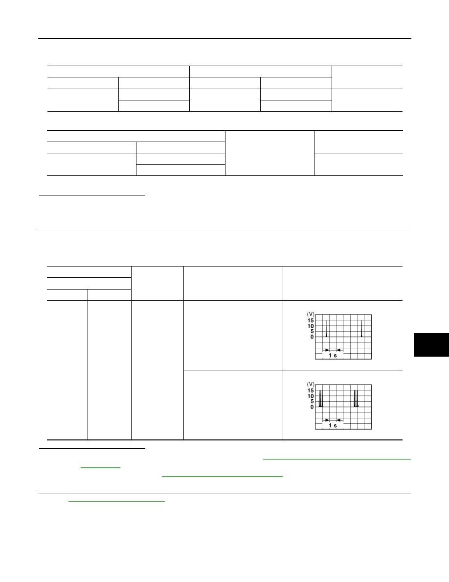
(+)
(–)
Condition
Signal
(Reference value.)
BCM
Connector
Terminal
M121
34, 35
Ground
Place Intelligent Key inside the ve-
hicle.
Place Intelligent Key outside the
vehicle.
JMKIA0062GB
JMKIA0063GB