Nissan Teana J32. Manual - part 231
BRAKE MASTER CYLINDER
BR-27
< ON-VEHICLE REPAIR >
C
D
E
G
H
I
J
K
L
M
A
B
BR
N
O
P
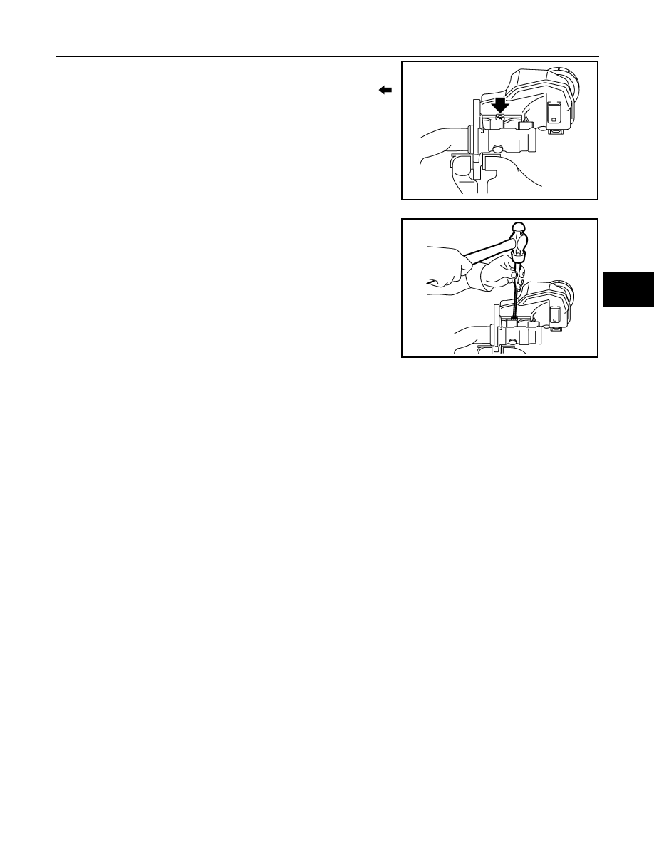
3.
Fix the cylinder body to a vise.
CAUTION:
• Place the reservoir tank with the chamfered pin hole (
)
facing up.
• Always set copper plates or cloth between vise when fix-
ing the cylinder body to a vise. Never overtighten the vise.
4.
Tilt the reservoir tank so that a mounting pin can be inserted.
Insert a mounting pin. Return the reservoir tank to the horizontal
position. Insert another mounting pin into the pin hole on the
opposite side in the same manner after the mounting pin passes
through the cylinder body pin hole.
CAUTION:
Never reuse the mounting pin.
Inspection
INFOID:0000000003811197
INSPECTION AFTER INSTALLATION
Fluid Leak
Check for brake fluid leakage from the cylinder body-to-brake booster mounting face, reservoir tank mounting
face and brake tube connections.
JPFIA0349ZZ
JPFIA0348ZZ