Nissan Teana J32. Manual - part 218
BCS-54
< ECU DIAGNOSIS >
BCM (BODY CONTROL MODULE)
79
(G)
Ground
Room antenna 1 (+)
(instrument panel)
Output
Ignition switch
OFF
When Intelligent Key is in
the passenger compart-
ment
When Intelligent Key is
not in the passenger
compartment
80
(G/O)
Ground
NATS antenna amp
(built in key slot)
Input/
Output
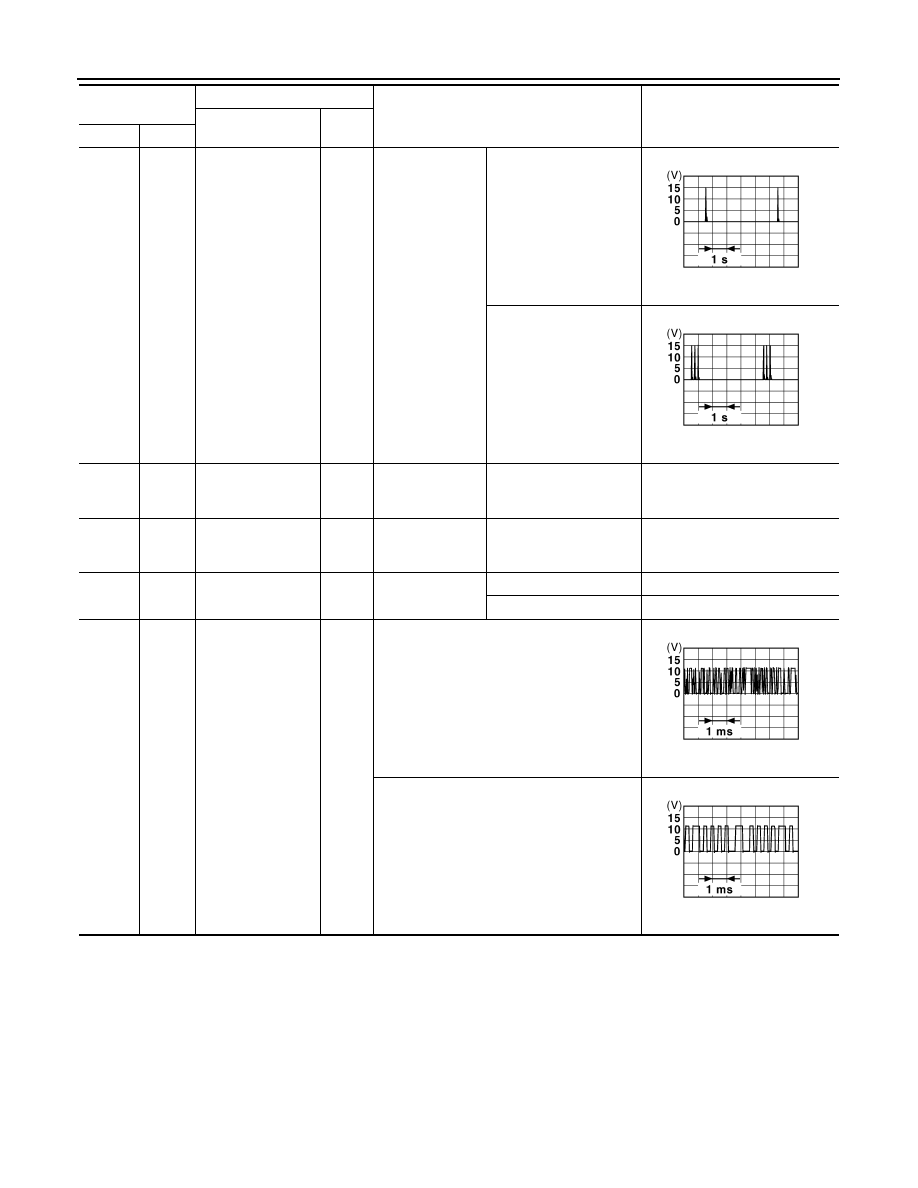
During waiting
Ignition switch is pressed
while inserting the key
into the key slot.
Just after pressing ignition
switch. Pointer of tester should
move.
81
(O)
Ground
NATS antenna amp
(built in key slot)
Input/
Output
During waiting
Ignition switch is pressed
while inserting the key
into the key slot.
Just after pressing ignition
switch. Pointer of tester should
move.
82
(R/B)
Ground
Ignition relay [fuse
block (J/B)] control
Output
Ignition switch
OFF or ACC
0 V
ON
Battery voltage
83
(L/O)
Ground
Remote keyless en-
try receiver commu-
nication
Input/
Output
During waiting
When operating either button on the key
Terminal No.
(Wire color)
Description
Condition
Value
(Approx.)
Signal name
Input/
Output
+
–
JMKIA0062GB
JMKIA0063GB
JMKIA0064GB
JMKIA0065GB