Nissan Teana J32. Manual - part 214
BCS-38
< COMPONENT DIAGNOSIS >
COMBINATION SWITCH INPUT CIRCUIT
COMBINATION SWITCH INPUT CIRCUIT
Diagnosis Procedure
INFOID:0000000003809625
1.
CHECK INPUT 1 - 5 SYSTEM CIRCUIT FOR OPEN
1.
Turn the ignition switch OFF.
2.
Disconnect the BCM and combination switch connectors.
3.
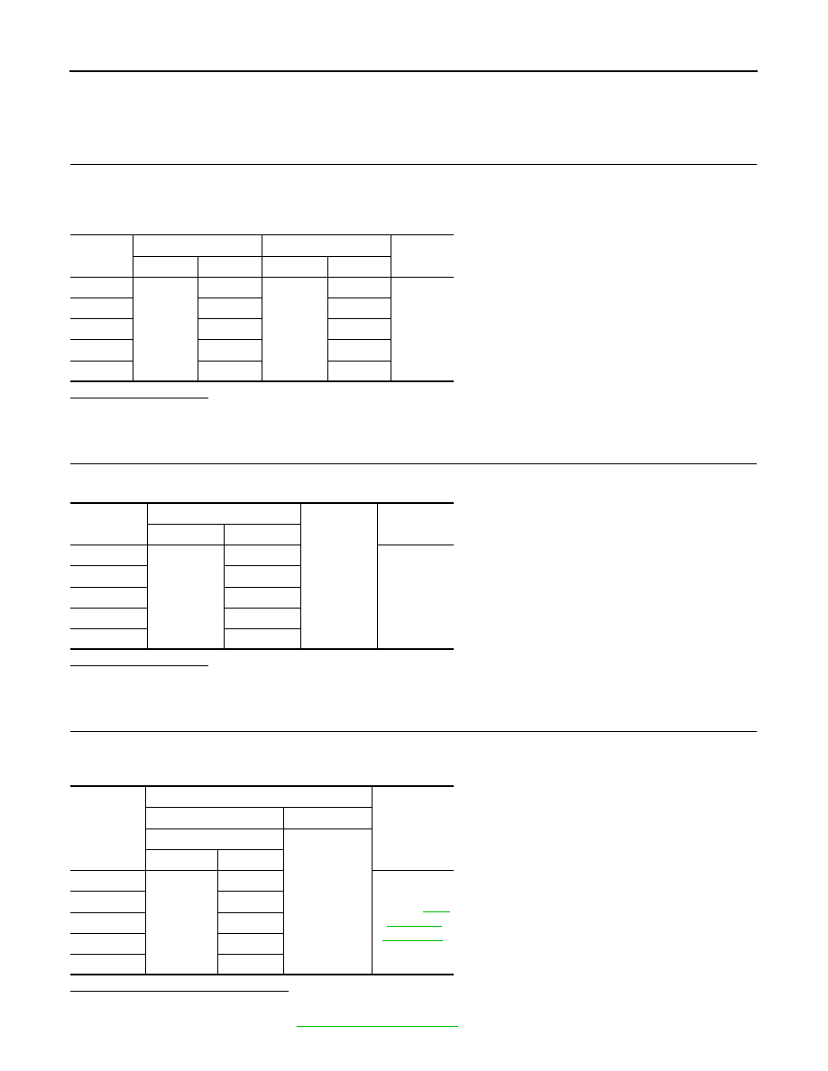
Check continuity between BCM harness connector and combination switch harness connector.
Does continuity exist?
YES
>> GO TO 2.
NO
>> Repair the harnesses or connectors.
2.
CHECK INPUT 1 - 5 SYSTEM CIRCUIT FOR SHORT
Check for continuity between BCM harness connector and ground.
Does continuity exist?
YES
>> Repair the harnesses or connectors.
NO
>> GO TO 3.
3.
CHECK BCM OUTPUT VOLTAGE
1.
Connect the BCM connector.
2.
Check voltage between BCM harness connector and ground.
Is the measurement value normal?
YES
>> GO TO 4.
NO
>> Replace BCM. Refer to
System
BCM
Combination switch
Continuity
Connector
Terminal
Connector
Terminal
INPUT 1
M122
107
M103
11
Existed
INPUT 2
109
9
INPUT 3
88
7
INPUT 4
108
10
INPUT 5
87
13
System
BCM
Ground
Continuity
Connector
Terminal
INPUT 1
M122
107
Not existed
INPUT 2
109
INPUT 3
88
INPUT 4
108
INPUT 5
87
System
Terminals
Voltage
(Approx.)
(+)
(
−
)
BCM
Ground
Connector
Terminal
INPUT 1
M122
107
Refer to
.
INPUT 2
109
INPUT 3
88
INPUT 4
108
INPUT 5
87