Nissan Teana J32. Manual - part 124


  Index      Nissan     Nissan Teana J32 (2008 year) - Service and Repair Manual


Search            


Content   ..  122  123  124  125   ..


Nissan Teana J32. Manual - part 124


AV

CAMERA CONTROL UNIT

AV-351

< ECU DIAGNOSIS >

[BOSE AUDIO WITHOUT NAVIGATION]

C

D

E

F

G

H

I

J

K

L

M

B

A

O

P

CAMERA CONTROL UNIT

Reference Values

INFOID:0000000003793617
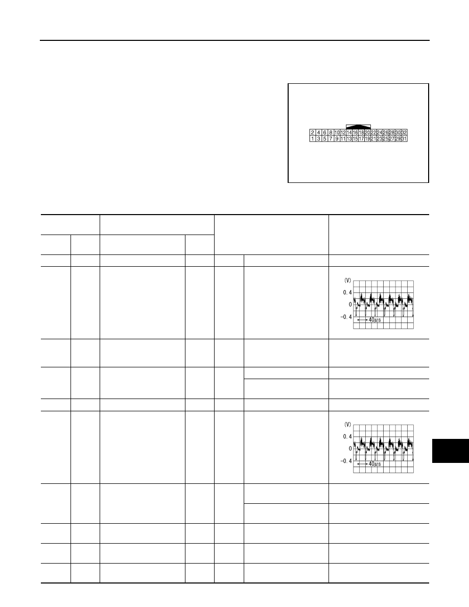
TERMINAL LAYOUT

PHYSICAL VALUES

JPNIA0007ZZ

Terminal

(Wire color)

Description

Condition

Reference value

(Approx.)

+

Signal name

Input/

Output

5

Shield

6

(B)

Ground

Camera image signal

Input

Ignition 

switch 

ON

When rear view camera im-
age is displayed.

7

(W)

Ground

Rear view camera ground

Ignition 

switch 

ON

0  V

8

(R)

Ground

Camera power supply

Output

Ignition 

switch 

ON 

Selector lever in R position.

6.0 V

Other than selector lever in 
R position.

0 V

11

Shield

12

(BR)

Ground

Camera image signal

Output

Ignition 

switch 

ON

When rear view camera im-
age is displayed.

14

(GR)

Ground

Camera connection recog-
nition signal

Output

Ignition 

switch 

ON

Connected to camera con-
trol unit connector.

0 V

Not connected to camera 
control unit connector.

5.0 V

17

(L/G)

AV communication signal 
(L)

Input/

Output

18

(L/R)

AV communication signal 
(H)

Input/

Output

19

(P)

AV communication signal 
(L)

Input/

Output

SKIB2251J

SKIB2251J

AV-352

< ECU DIAGNOSIS >

[BOSE AUDIO WITHOUT NAVIGATION]

CAMERA CONTROL UNIT

20

(L)

AV communication signal 
(H)

Input/

Output

22

(W)

Ground

Reverse signal

Input

Ignition 

switch 

ON

Selector lever in R position.

12.0 V

Other than selector lever in 
R position.

0 V

23

(G)

Ground

Sensor signal 1

Input

Ignition 

switch 

ON

Turn the steering to the 
right.

A: Sensor signal 1
B: Sensor signal 2

Turn the steering to the left.

A: Sensor signal 1
B: Sensor signal 2

24

(SB)

Ground

Sensor signal 2

Input

Ignition 

switch 

ON

Turn the steering to the 
right.

A: Sensor signal 1
B: Sensor signal 2

Turn the steering to the left.

A: Sensor signal 1
B: Sensor signal 2

25

(O)

Ground

Sensor signal 3

Input

Ignition 

switch 

ON

Turn the steering around 
the neutral position.

A: Sensor signal 3
B: Sensor signal 1

Terminal

(Wire color)

Description

Condition

Reference value

(Approx.)

+

Signal name

Input/

Output

SKIB3827E

SKIB3828E

SKIB3827E

SKIB3828E

SKIB3829E

AV

CAMERA CONTROL UNIT

AV-353

< ECU DIAGNOSIS >

[BOSE AUDIO WITHOUT NAVIGATION]

C

D

E

F

G

H

I

J

K

L

M

B

A

O

P

26

(O)

Ground

Vehicle speed signal
(8-pulse)

Input

Ignition 

switch 

ON

When vehicle speed is ap-
prox. 40 km/h (25 MPH).

NOTE:
The maximum voltage varies de-
pending on the specification 
(destination unit).

30

(V)

Ground

ACC power supply

Input

Ignition 

switch 

ACC

Battery voltage

31

(B/R)

Ground

Ground

Ignition 

switch 

ON

0  V

32

(Y)

Ground

Battery power supply

Input

Ignition 

switch 

OFF

Battery voltage

Terminal

(Wire color)

Description

Condition

Reference value

(Approx.)

+

Signal name

Input/

Output

SKIA6649J

AV-354

< ECU DIAGNOSIS >

[BOSE AUDIO WITHOUT NAVIGATION]

CAMERA CONTROL UNIT

Wiring Diagram — BOSE AUDIO WITHOUT NAVIGATION SYSTEM —

INFOID:0000000003971972

JCNWM0917GB


Content   ..  122  123  124  125   ..