Nissan Teana J32. Manual - part 1220


  Index      Nissan     Nissan Teana J32 (2008 year) - Service and Repair Manual


Search            


Content   ..  1218  1219  1220  1221   ..


Nissan Teana J32. Manual - part 1220


VTL-66

< PRECAUTION >

[WITH 7 INCH DISPLAY]

PRECAUTIONS

Ventilate work area before resuming service if accidental system discharge occurs. Additional health
and safety information may be obtained from refrigerant and lubricant manufacturers.

• Never release refrigerant into the air. Use approved recovery/recycling equipment to capture the

refrigerant each time an air conditioning system is discharged.

• Wear always eye and hand protection (goggles and gloves) when working with any refrigerant or air

conditioning system.

• Never store or heat refrigerant containers above 52

°

C (126

°

F).

• Never heat a refrigerant container with an open flame; Place the bottom of the container in a warm

pail of water if container warming is required.

• Never intentionally drop, puncture, or incinerate refrigerant containers.
• Keep refrigerant away from open flames: poisonous gas is produced if refrigerant burns.
• Refrigerant displaces oxygen, therefore be certain to work in well ventilated areas to prevent suffo-

cation.

• Never pressure test or leakage test HFC-134a (R-134a) service equipment and/or vehicle air condi-

tioning systems with compressed air during repair. Some mixtures of air and HFC-134a (R-134a)
have been shown to be combustible at elevated pressures. These mixtures, if ignited, may cause
injury or property damage. Additional health and safety information may be obtained from refriger-
ant manufacturers.

Refrigerant Connection

INFOID:0000000003894451

A new type refrigerant connection has been introduced to all refrigerant lines except the following locations.
• Expansion valve to evaporator
• Refrigerant pressure sensor to liquid tank

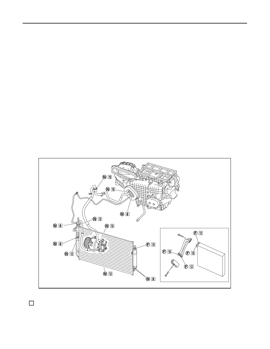
O-RING AND REFRIGERANT CONNECTION

CAUTION:

The new and former refrigerant connections use different O-ring configurations. Never confuse O-
rings since they are not interchangeable. Refrigerant may leak at the connection if a wrong O-ring is
installed.

F.

Former type refrigerant connection

N.

New type refrigerant connection

: O-ring size

JPIIA0986ZZ

PRECAUTIONS

VTL-67

< PRECAUTION >

[WITH 7 INCH DISPLAY]

C

D

E

F

G

H

J

K

L

M

A

B

VTL

N

O

P

O-Ring Part Numbers and Specifications

WARNING:

Check that all refrigerant is discharged into the recycling equipment and the pressure in the system is
less than atmospheric pressure. Then gradually loosen the discharge side hose fitting and remove it.

CAUTION:

Observe the following when replacing or cleaning refrigerant cycle components.
• Store it in the same way at it is when mounted on the car when the compressor is removed. Failure

to do so causes lubricant to enter the low-pressure chamber.

• Use always a torque wrench and a back-up wrench when connecting tubes.
• Plug immediately all openings to prevent entry of dust and moisture after disconnecting tubes.
• Connect the pipes at the final stage of the operation when installing an air conditioner in the vehicle.

Never remove the seal caps of pipes and other components until just before required for connection.

• Allow components stored in cool areas to warm to working area temperature before removing seal

caps. This prevents condensation from forming inside A/C components.

• Remove thoroughly moisture from the refrigeration system before charging the refrigerant.
• Replace always used O-rings.
• Apply lubricant to circle of the O-rings shown in illustration when connecting tube. Be careful not to

apply lubricant to threaded portion.

• O-ring must be closely attached to the groove portion of tube.
• Be careful not to damage O-ring and tube when replacing the O-ring.
• Connect tube until a click can be heard. Then tighten the nut or bolt by hand. Check that the O-ring is

installed to tube correctly.

Connection type

Piping connection point

Part number

QTY

O-ring size

New

Low-pressure flexible hose to low-pressure pipe

92474 N8210

1

19

High-pressure pipe to condenser pipe assembly (Outlet)

92471 N8210

1

8

Condenser pipe assembly (Inlet) to high-pressure flexible 
hose

92472 N8210

1

12

Condenser assembly to condenser pipe as-
sembly

Inlet

92472 N8210

1

12

Outlet

92471 N8210

1

8

Low-pressure pipe to expansion valve

92473 N8210

1

16

High-pressure pipe to expansion valve

92471 N8210

1

8

Compressor to low-pressure flexible hose

92474 N8210

1

19

Compressor to high-pressure flexible hose

92472 N8210

1

12

Liquid tank to condenser assembly

Inlet

92471 N8210

1

8

Outlet

1

Former

Refrigerant pressure sensor to liquid tank

J2476 89956

1

10

Expansion valve to evaporator pipe assembly

Inlet

92475 71L00

1

12

Outlet

92475 72L00

1

16

Evaporator to evaporator pipe assembly

Inlet

92475 71L00

1

12

Outlet

92475 72L00

1

16

Name

: NISSAN A/C System Oil Type S

VTL-68

< PRECAUTION >

[WITH 7 INCH DISPLAY]

PRECAUTIONS

• Perform leakage test and make sure that there is no leakage from connections after connecting line.

Disconnect that line and replace the O-ring when the refrigerant leaking point is found. Then tighten
connections of seal seat to the specified torque.

Service Equipment

INFOID:0000000003894452

RECOVERY/RECYCLING EQUIPMENT

Be certain to follow the manufacturer’s instructions for machine operation and machine maintenance. Never
introduce any refrigerant other than that specified into the machine.

ELECTRICAL LEAK DETECTOR

Be certain to follow the manufacturer’s instructions for tester operation and tester maintenance.

VACUUM PUMP

The lubricant contained inside the vacuum pump is not compatible
with the specified lubricant for HFC-134a (R-134a) A/C systems.
The vent side of the vacuum pump is exposed to atmospheric pres-
sure. So the vacuum pump lubricant may migrate out of the pump
into the service hose. This is possible when the pump is switched
OFF after evacuation (vacuuming) and hose is connected to it.
To prevent this migration, use a manual valve placed near the hose-
to-pump connection, as per the following.
• Vacuum pumps usually have a manual isolator valve as part of the

pump. Close this valve to isolate the service hose from the pump.

• Use a hose equipped with a manual shut-off valve near the pump

end for pumps without an isolator. Close the valve to isolate the
hose from the pump.

• Disconnect the hose from the pump if the hose has an automatic

shut-off valve. As long as the hose is connected, the valve is open
and lubricating oil may migrate.

Some one-way valves open when vacuum is applied and close
under no vacuum condition. Such valves may restrict the pump’s
ability to pull a deep vacuum and are not recommended.

MANIFOLD GAUGE SET

RHA861F

RHA270DA

PRECAUTIONS

VTL-69

< PRECAUTION >

[WITH 7 INCH DISPLAY]

C

D

E

F

G

H

J

K

L

M

A

B

VTL

N

O

P

Be certain that the gauge face indicates HFC-134a or R-134a. Be
sure the gauge set has 1/2

-16 ACME threaded connections for ser-

vice hoses. Confirm the set has been used only with refrigerant
HFC-134a (R-134a) and specified lubricants.

SERVICE HOSES

Be certain that the service hoses display the markings described
(colored hose with black stripe). All hoses must equip positive shut-
off devices (either manual or automatic) near the end of the hoses
opposite to the manifold gauge.

SERVICE COUPLERS

Never attempt to connect HFC-134a (R-134a) service couplers to a
CFC-12 (R-12) A/C system. The HFC-134a (R-134a) couplers do
not properly connect to the CFC-12 (R-12) system. However, if an
improper connection is attempted, discharging and contamination
may occur.

REFRIGERANT WEIGHT SCALE

Verify that no refrigerant other than HFC-134a (R-134a) and speci-
fied lubricants have been used with the scale. The hose fitting must
be 1/2

-16 ACME if the scale controls refrigerant flow electronically.

CALIBRATING ACR4 WEIGHT SCALE

Calibrate the scale each three month.
To calibrate the weight scale on the ACR4:

1.

Press “Shift/Reset” and “Enter” at the same time.

2.

Press “8787”“A1” is displayed.

3.

Remove all weight from the scale.

4.

Press “0”, then press “Enter”“0.00” is displayed and change to “A2”.

SHA533D

RHA272D

Shut-off valve rotation

A/C service valve

Clockwise

Open

Counterclockwise

Close

RHA273D

RHA274D


Content   ..  1218  1219  1220  1221   ..