Content .. 1155 1156 1157 1158 ..
Nissan Teana J32. Manual - part 1157
TM-152
< ON-VEHICLE MAINTENANCE >
[CVT: RE0F09B]
CVT POSITION
CVT POSITION
Inspection and Adjustment
INFOID:0000000003849084
INSPECTION
1.
Move selector lever to “P” position, and turn ignition switch ON (engine stop).
2.
Check that selector lever can be shifted to other than “P” position when brake pedal is depressed. Also
check that selector lever can be shifted from “P” position only when brake pedal is depressed.
3.
Move selector lever and check for excessive effort, sticking, noise or rattle.
4.
Check that selector lever stops at each position with the feel of engagement when it is moved through all
the positions. Check that the actual position of selector lever matches the position shown by shift position
indicator and manual lever on the transaxle.
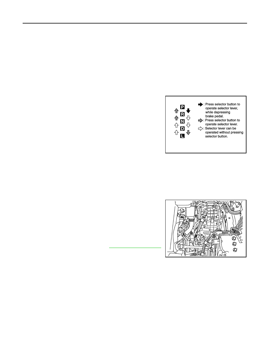
5.
The method of operating selector lever to individual positions
correctly should be as shown.
6.
When selector button is pressed in “P”, “R”, “N”, “D” or “L” posi-
tion without applying forward/backward force to selector lever,
check button operation for sticking.
7.
Check that back-up lamps illuminate only when selector lever is
placed in the “R” position.
8.
When in “R” position, check that back-up lamps illuminate even
when the selector lever is pushed toward the “P” position.
CAUTION:
Check the lighting without pressing shift button.
9.
Check that back-up lamps do not illuminate when selector lever is pushed toward the “R” position when in
the “P” or “N” position.
CAUTION:
Check the lighting without pressing shift button.
10. Check that the engine can only be started with selector lever in the “P” and “N” positions.
11. Check that transaxle is locked completely in “P” position.
ADJUSTMENT
1.
Move selector lever to “ P” position.
CAUTION:
Turn wheels more than 1/4 rotations and apply the park
lock.
2.
Loosen the control cable nut (A).
3.
Place manual lever (B) to “P” position.
CAUTION:
Never apply any force to manual lever.
4.
Tighten the control cable nut. Refer to
.
CAUTION:
Fix manual lever when tightening.
JPDIA0343GB
JPDIA0794ZZ