Nissan Teana J32. Manual - part 1110


  Index      Nissan     Nissan Teana J32 (2008 year) - Service and Repair Manual


Search            


Content   ..  1108  1109  1110  1111   ..


Nissan Teana J32. Manual - part 1110


ENGINE SPEED SIGNAL CIRCUIT

STC-9

< COMPONENT DIAGNOSIS >

C

D

E

F

H

I

J

K

L

M

A

B

STC

N

O

P

ENGINE SPEED SIGNAL CIRCUIT

Description

INFOID:0000000003893531

ECM sends engine speed signal to power steering control unit.

Diagnosis Procedure

INFOID:0000000003893532

1.

PERFORM ECM SELF-DIAGNOSIS

With CONSULT-III

1.

Turn the ignition switch ON.

Perform ECM self-diagnosis. Refer to 

EC-113, "CONSULT-III Function"

.

Is any DTC detected?

YES

>> Check the DTC.

NO

>> GO TO 2.

2.

CHECK HARNESS BETWEEN ECM AND POWER STEERING CONTROL UNIT

1.

Turn the ignition switch OFF.

2.

Disconnect ECM harness connectors.

3.

Disconnect power steering control unit harness connector.

4.

Check continuity between ECM harness connector and power steering control unit harness connector.

5.

Check continuity between power steering control unit harness connector and ground.

Is the inspection result normal?

YES

>> GO TO 3.

NO

>> Repair or replace damaged parts.

3.

CHECK ENGINE SPEED SIGNAL (1)

1.

Connect ECM harness connectors.

2.

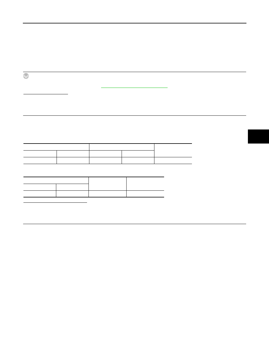
Check signal between ECM harness connector and ground with oscilloscope.

ECM

Power steering control unit

Continuity

Connector

Terminal

Connector

Terminal

E16

94

M61

10

Existed

Power steering control unit

Continuity

Connector

Terminal

M61

10

Ground

Not existed

STC-10

< COMPONENT DIAGNOSIS >

ENGINE SPEED SIGNAL CIRCUIT

Is the inspection result normal?

YES

>> GO TO 4.

NO

>> Replace ECM. Refer to 

EC-14, "ADDITIONAL SERVICE WHEN REPLACING CONTROL UNIT :

Description"

.

4.

CHECK ENGINE SPEED SIGNAL (2)

1.

Connect power steering control unit harness connector.

2.

Check signal between power steering control unit harness connector and ground with oscilloscope.

Is the inspection result normal?

YES

>> GO TO 5.

NO

>> Replace power steering control unit. Refer to 

STC-19, "Exploded View"

.

5.

CHECK TERMINALS AND HARNESS CONNECTORS

• Check power steering control unit pin terminals for damage or loose connection with harness connector.
• Check ECM pin terminals for damage or loose connection with harness connector.
Is the inspection result normal?

YES

>> INSPECTION END

NO

>> Repair or replace damaged parts.

ECM

Condition

Voltage (Approx.)

Connector

Terminal

E16

94

Ground

Engine is running
• Warm-up condition
• Idle speed

Engine is running
• Warm-up condition
• Engine speed: Approx. 2,000 rpm

JSGIA0143ZZ

PBIA3655J

Power steering control unit

Condition

Voltage (Approx.)

Connector

Terminal

M61

10

Ground

Engine is running
• Warm-up condition
• Idle speed

Engine is running
• Warm-up condition
• Engine speed: Approx. 2,000 rpm

JSGIA0143ZZ

PBIA3655J

VEHICLE SPEED SIGNAL CIRCUIT

STC-11

< COMPONENT DIAGNOSIS >

C

D

E

F

H

I

J

K

L

M

A

B

STC

N

O

P

VEHICLE SPEED SIGNAL CIRCUIT

Description

INFOID:0000000003893533

Combination meter sends vehicle speed signal to power steering control unit.

Diagnosis Procedure

INFOID:0000000003893534

1.

PERFORM COMBINATION METER SELF-DIAGNOSIS

With CONSULT-III

1.

Turn the ignition switch ON.

2.

Perform combination meter self-diagnosis. Refer to 

MWI-33, "CONSULT-III Function (METER/M&A)"

.

Is any DTC detected?

YES

>> Check the DTC.

NO

>> GO TO 2.

2.

CHECK HARNESS BETWEEN COMBINATION METER AND POWER STEERING CONTROL UNIT

1.

Turn the ignition switch OFF.

2.

Disconnect combination meter harness connector.

3.

Disconnect power steering control unit harness connector.

4.

Check continuity between combination meter harness connector and power steering control unit harness
connector.

5.

Check continuity between power steering control unit harness connector and ground.

Is the inspection result normal?

YES

>> GO TO 3.

NO

>> Repair or replace damaged parts.

3.

CHECK VEHICLE SPEED SIGNAL (1)

1.

Connect combination meter harness connector.

2.

Check combination meter input/output standard values. Refer to 

MWI-53, "Reference Value"

.

Is the inspection result normal?

YES

>> GO TO 4.

NO

>> Replace combination meter Refer to 

MWI-126, "Exploded View"

.

4.

CHECK VEHICLE SPEED SIGNAL (2)

1.

Connect power steering control unit harness connector.

2.

Check signal between power steering control unit harness connector and ground with oscilloscope.

Combination meter

Power steering control unit

Continuity

Connector

Terminal

Connector

Terminal

M34

30

M61

8

Existed

Power steering control unit

Continuity

Connector

Terminal

M61

8

Ground

Not existed

STC-12

< COMPONENT DIAGNOSIS >

VEHICLE SPEED SIGNAL CIRCUIT

Is the inspection result normal?

YES

>> GO TO 5.

NO

>> Replace power steering control unit. Refer to 

STC-19, "Exploded View"

.

5.

CHECK TERMINALS AND HARNESS CONNECTORS

• Check power steering control unit pin terminals for damage or loose connection with harness connector.
• Check combination meter pin terminals for damage or loose connection with harness connector.
Is the inspection result normal?

YES

>> INSPECTION END

NO

>> Repair or replace damaged parts.

Power steering control unit

Condition

Voltage (Approx.)

Connector

Terminal

M61

 8

Ground

Vehicle speed: 40 km/h (25 MPH)

CAUTION:

Check air pressure of tire under 
standard condition.

JSNIA0015GB


Content   ..  1108  1109  1110  1111   ..