Nissan Teana J32. Manual - part 1054


  Index      Nissan     Nissan Teana J32 (2008 year) - Service and Repair Manual


Search            


Content   ..  1052  1053  1054  1055   ..


Nissan Teana J32. Manual - part 1054


SEC-204

< ON-VEHICLE REPAIR >

[INTELLIGENT KEY SYSTEM]

KEY SLOT

ON-VEHICLE REPAIR

KEY SLOT

Removal and Installation

INFOID:0000000003815119

REMOVAL

1.

Remove the instrument lower panel LH. Refer to 

IP-12,

"Removal and Installation"

.

2.

Disconnect key slot connector.

3.

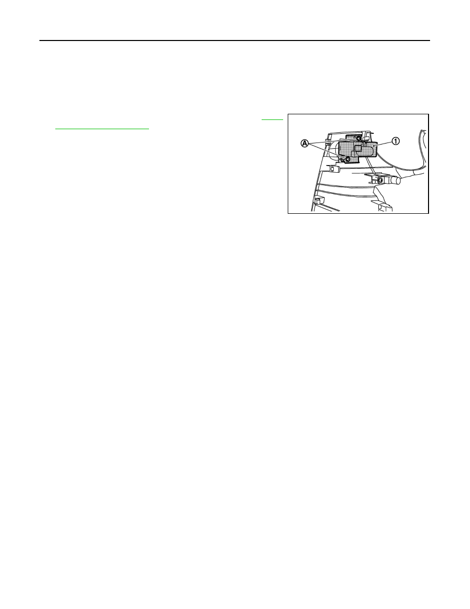
Remove the key slot mounting screw (A), and then remove key
slot (1) from instrument lower panel LH.

INSTALLATION

Install in the reverse order of removal.

JMKIA2351ZZ

PUSH BUTTON IGNITION SWITCH

SEC-205

< ON-VEHICLE REPAIR >

[INTELLIGENT KEY SYSTEM]

C

D

E

F

G

H

I

J

L

M

A

B

SEC

N

O

P

PUSH BUTTON IGNITION SWITCH

Removal and Installation

INFOID:0000000003839086

REMOVAL

Remove the push-button ignition switch fixing pawl using a remover
tool (A), and then remove push-button ignition switch (1).

INSTALLATION

Install in the reverse order of removal.

JMMIA0014ZZ

SR-1

RESTRAINTS

C

D

E

F

G

I

J

K

L

M

SECTION 

SR

A

B

SR

N

O

P

CONTENTS

SRS AIRBAG

PRECAUTION ...............................................

2

PRECAUTIONS ...................................................

2

Precaution for Supplemental Restraint System 
(SRS) "AIR BAG" and "SEAT BELT PRE-TEN-
SIONER" .................................................................
..

2

Precaution Necessary for Steering Wheel Rota-
tion after Battery Disconnect  ...................................
..

2

Service ......................................................................

2

Occupant Classification System ..............................

3

PREPARATION ............................................

4

PREPARATION ...................................................

4

Special Service Tool  .................................................

4

Commercial Service Tool  ..........................................

5

ON-VEHICLE REPAIR ..................................

6

DRIVER AIR BAG MODULE ...............................

6

Exploded View  ..........................................................

6

Removal and Installation ...........................................

6

SPIRAL CABLE  ..................................................

9

Exploded View  ..........................................................

9

Removal and Installation ...........................................

9

FRONT PASSENGER AIR BAG MODULE  .......

12

Exploded View  ........................................................

12

Removal and Installation  .........................................

12

SIDE CURTAIN AIR BAG MODULE  ................

14

Exploded View .........................................................

14

Removal and Installation  .........................................

14

FRONT SIDE AIR BAG MODULE  ....................

16

Exploded View .........................................................

16

Removal and Installation  .........................................

16

CRASH ZONE SENSOR ...................................

18

Exploded View .........................................................

18

Removal and Installation  .........................................

18

SIDE AIR BAG (SATELLITE) SENSOR  ...........

20

Exploded View .........................................................

20

Removal and Installation  .........................................

20

DIAGNOSIS SENSOR UNIT  .............................

22

Exploded View .........................................................

22

Removal and Installation  .........................................

22

FRONT SEAT BELT PRE-TENSIONER  ...........

24

Removal and Installation  .........................................

24

DISPOSAL OF AIR BAG MODULE AND 
SEAT BELT PRE-TENSIONER  ........................

25

Caution for Air Bag Module and Seat Belt Pre-ten-
sioner .......................................................................

25

SR-2

< PRECAUTION >

PRECAUTIONS

PRECAUTION

PRECAUTIONS

Precaution for Supplemental Restraint System (SRS) "AIR BAG" and "SEAT BELT 
PRE-TENSIONER"

INFOID:0000000003838497

The Supplemental Restraint System such as “AIR BAG” and “SEAT BELT PRE-TENSIONER”, used along
with a front seat belt, helps to reduce the risk or severity of injury to the driver and front passenger for certain
types of collision. Information necessary to service the system safely is included in the “SRS AIRBAG” and
“SEAT BELT” of this Service Manual.

WARNING:

• To avoid rendering the SRS inoperative, which could increase the risk of personal injury or death in

the event of a collision which would result in air bag inflation, all maintenance must be performed by
an authorized NISSAN/INFINITI dealer.

• Improper maintenance, including incorrect removal and installation of the SRS, can lead to personal

injury caused by unintentional activation of the system. For removal of Spiral Cable and Air Bag
Module, see the “SRS AIRBAG”.

• Never use electrical test equipment on any circuit related to the SRS unless instructed to in this Ser-

vice Manual. SRS wiring harnesses can be identified by yellow and/or orange harnesses or harness
connectors.

Precaution Necessary for Steering Wheel Rotation after Battery Disconnect

INFOID:0000000003838498

NOTE:
• Before removing and installing any control units, first turn the push-button ignition switch to the LOCK posi-

tion, then disconnect both battery cables.

• After finishing work, confirm that all control unit connectors are connected properly, then re-connect both

battery cables.

• Always use CONSULT-III to perform self-diagnosis as a part of each function inspection after finishing work.

If a DTC is detected, perform trouble diagnosis according to self-diagnosis results.

This vehicle is equipped with a push-button ignition switch and a steering lock unit.
If the battery is disconnected or discharged, the steering wheel will lock and cannot be turned.
If turning the steering wheel is required with the battery disconnected or discharged, follow the procedure
below before starting the repair operation.

OPERATION PROCEDURE

1.

Connect both battery cables.
NOTE:
Supply power using jumper cables if battery is discharged.

2.

Turn the push-button ignition switch to ACC position.
(At this time, the steering lock will be released.)

3.

Disconnect both battery cables. The steering lock will remain released with both battery cables discon-
nected and the steering wheel can be turned.

4.

Perform the necessary repair operation.

5.

When the repair work is completed, re-connect both battery cables. With the brake pedal released, turn
the push-button ignition switch from ACC position to ON position, then to LOCK position. (The steering
wheel will lock when the push-button ignition switch is turned to LOCK position.)

6.

Perform self-diagnosis check of all control units using CONSULT-III.

Service

INFOID:0000000003751420

• Do not use electrical test equipment to check SRS circuits unless instructed to in this Service Manual.
• Before servicing the SRS, turn ignition switch OFF, disconnect both battery cables and wait at least 3 min-

utes.
For approximately 3 minutes after the cables are removed, it is still possible for the air bag and seat belt pre-
tensioner to deploy. Therefore, do not work on any SRS connectors or wires until at least 3 minutes have
elapsed.


Content   ..  1052  1053  1054  1055   ..