Nissan Teana J32. Manual - part 92
AV
U1243 DISPLAY UNIT
AV-223
< COMPONENT DIAGNOSIS >
[BOSE AUDIO WITHOUT NAVIGATION]
C
D
E
F
G
H
I
J
K
L
M
B
A
O
P
3.
CHECK COMMUNICATION SIGNAL
1.
Connect display unit connector and AV control unit connector.
2.
Turn ignition switch ON.
3.
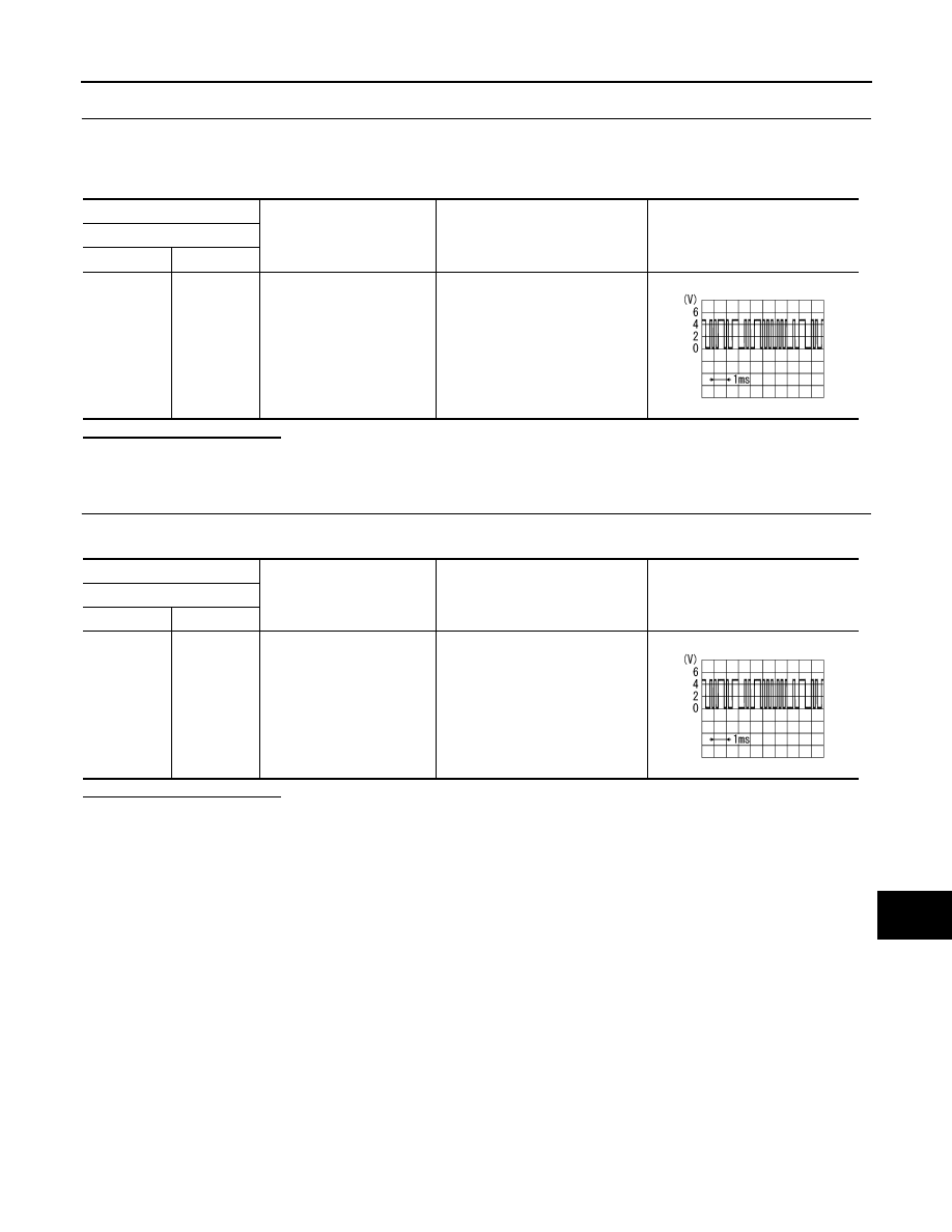
Check signal between display unit harness connector terminal and ground using an oscilloscope.
Is inspection result normal?
YES
>> GO TO 4.
NO
>> Replace AV control unit.
4.
CHECK COMMUNICATION SIGNAL
Check signal between display unit harness connector terminal and ground using an oscilloscope.
Is inspection result normal?
YES
>> INSPECTION END
NO
>> Replace display unit.
(+)
(
−
)
Condition
Reference value
Display unit
Connector
Terminal
M49
11
Ground
When adjusting display bright-
ness.
PKIB5039J
(+)
(
−
)
Condition
Reference value
Display unit
Connector
Terminal
M49
22
Ground
When adjusting display bright-
ness.
PKIB5039J