Nissan Teana J32. Manual - part 63
AV
AV CONTROL UNIT
AV-107
< ECU DIAGNOSIS >
[BASE AUDIO AND DISPLAY SYSTEM]
C
D
E
F
G
H
I
J
K
L
M
B
A
O
P
Terminal
(Wire color)
Description
Condition
Reference value
(Approx.)
+
–
Signal name
Input/
Output
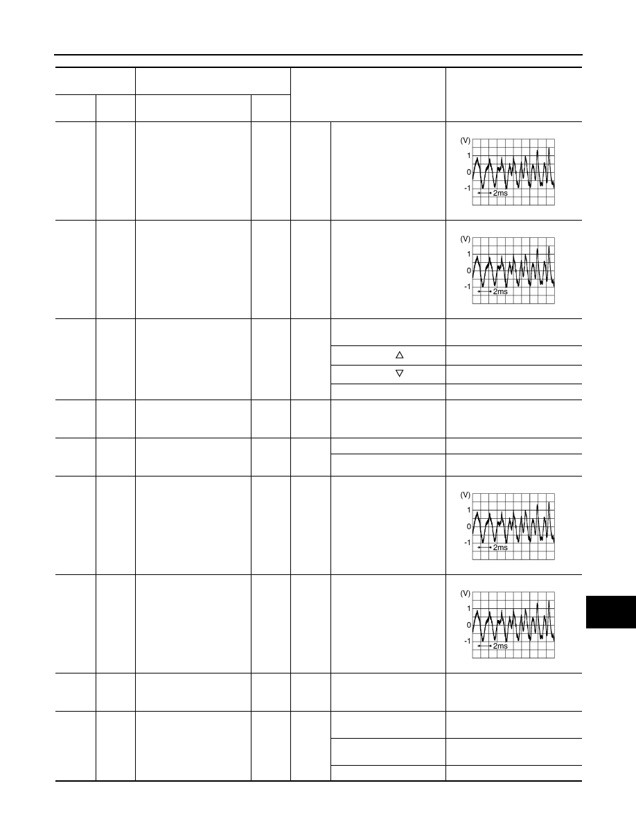
2
(W)
3
(B)
Sound signal front LH
Output
Ignition
switch
ON
Sound output.
4
(O/B)
5
(W/R)
Sound signal rear LH
Output
Ignition
switch
ON
Sound output.
6
(W/G)
15
(L/B)
Steering switch signal A
Input
Ignition
switch
ON
Keep pressing SOURCE
switch.
0 V
Keep pressing
switch.
0.7 V
Keep pressing
switch.
1.3 V
Except for above.
3.3 V
7
(V/W)
Ground
ACC power supply
Input
Ignition
switch
ACC
—
Battery voltage
9
(R/L)
Ground
Illumination signal
Input
Ignition
switch
OFF
Lighting switch is OFF.
0 V
Lighting switch is ON.
12.0 V
11
(B/W)
12
(BR)
Sound signal front RH
Output
Ignition
switch
ON
Sound output.
13
(L)
14
(B/W)
Sound signal rear RH
Output
Ignition
switch
ON
Sound output.
15
(L/B)
Ground
Steering switch signal
ground
—
Ignition
switch
ON
—
0 V
16
(GR/L)
15
(L/B)
Steering switch signal B
Input
Ignition
switch
ON
Keep pressing VOL DOWN
switch.
0 V
Keep pressing VOL UP
switch.
0.7 V
Except for above.
3.3 V
SKIB3609E
SKIB3609E
SKIB3609E
SKIB3609E