Nissan Teana J32. Manual - part 18
LIFTING SENSOR (FRONT)
ADP-65
< COMPONENT DIAGNOSIS >
C
D
E
F
G
H
I
K
L
M
A
B
ADP
N
O
P
4.
Check continuity between driver seat control unit harness connector and ground.
Is the inspection result normal?
YES
>> Replace driver seat control unit. Refer to
ADP-136, "Removal and Installation"
NO
>> Repair or replace harness.
3.
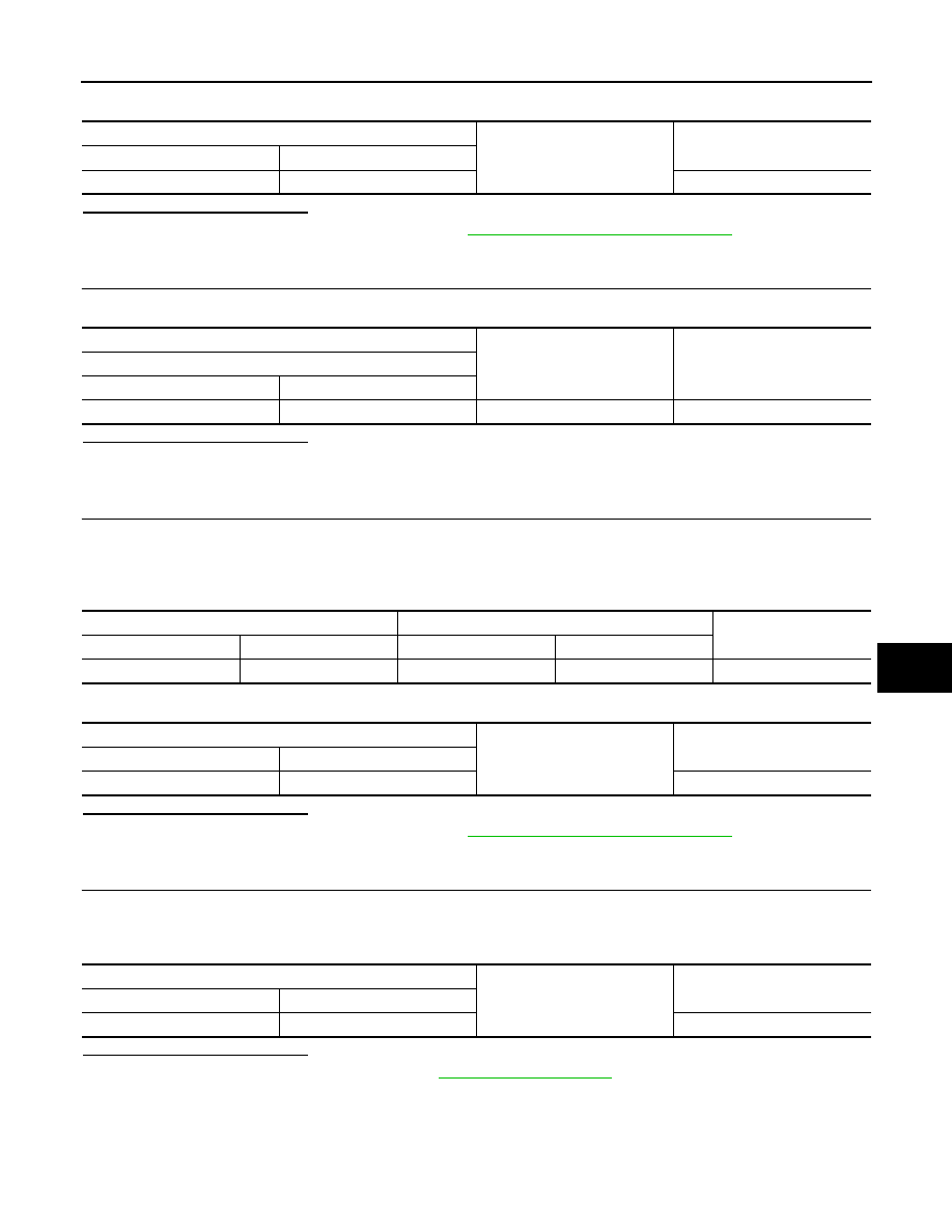
CHECK LIFTING SENSOR (FRONT) POWER SUPPLY
Check voltage between lifting motor (front) harness connector and ground.
Is the inspection result normal?
YES
>> GO TO 5.
NO
>> GO TO 4.
4.
CHECK LIFTING SENSOR (FRONT) POWER SUPPLY CIRCUIT
1.
Turn ignition switch OFF.
2.
Disconnect driver seat control unit connector and lifting motor (front) connector.
3.
Check continuity between driver seat control unit harness connector and lifting motor (front) harness con-
nector.
4.
Check continuity between driver seat control unit harness connector and ground.
Is the inspection result normal?
YES
>> Replace driver seat control unit. Refer to
ADP-136, "Removal and Installation"
NO
>> Repair or replace harness.
5.
CHECK LIFTING SENSOR (FRONT) GROUND
1.
Turn ignition switch OFF.
2.
Disconnect driver seat control unit connector and lifting motor (front) connector.
3.
Check continuity between lifting motor (front) harness connector and ground.
Is the inspection result normal?
YES
>> Replace lifting motor (front). Refer to
.
NO
>> Repair or replace harness.
Driver seat control unit
Ground
Continuity
Connector
Terminal
B452
22
Not existed
(+)
(–)
Voltage (V)
(Approx.)
Lifting motor (front)
Connector
Terminal
B455
34
Ground
Battery voltage
Driver seat control unit
Lifting motor (front)
Continuity
Connector
Terminal
Connector
Terminal
B452
31
B455
34
Existed
Driver seat control unit
Ground
Continuity
Connector
Terminal
B452
31
Not existed
Lifting motor (front)
Ground
Continuity
Connector
Terminal
B455
43
Existed