Nissan Teana J32. Manual - part 13
POWER SUPPLY AND GROUND CIRCUIT
ADP-45
< COMPONENT DIAGNOSIS >
C
D
E
F
G
H
I
K
L
M
A
B
ADP
N
O
P
POWER SUPPLY AND GROUND CIRCUIT
DRIVER SEAT CONTROL UNIT
DRIVER SEAT CONTROL UNIT : Diagnosis Procedure
INFOID:0000000003759115
NOTE:
Do not disconnect the battery negative terminal and the driver seat control unit connector until DTC is con-
firmed with CONSULT-III.
1.
CHECK FUSIBLE LINK
1.
Turn ignition switch OFF.
2.
Check that the following fusible link is not blown.
Is the fusible link blown?
YES
>> Replace the blown fusible link after repairing the affected circuit if a fusible link is blown.
NO
>> GO TO 2.
2.
CHECK POWER SUPPLY CIRCUIT
1.
Disconnect driver seat control unit connector.
2.
Check voltage between driver seat control unit harness connector and ground.
Is the inspection result normal?
YES
>> GO TO 3.
NO-1
>> Repair or replace harness.
NO-2
>> Check circuit breaker.
3.
CHECK GROUND CIRCUIT
Check continuity between the driver seat control unit harness connector and ground.
Is the inspection result normal?
YES
>> INSPECTION END
NO
>> Repair or replace harness.
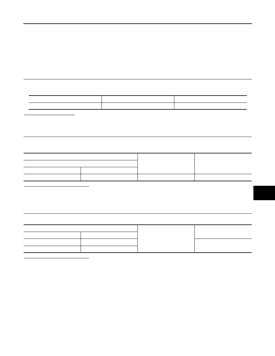
Terminal No.
Signal name
Fusible link No.
1
Battery power supply
I (40A)
(+)
(–)
Voltage (V)
(Approx.)
Driver seat control unit
Connector
Terminals
B451
1
Ground
Battery voltage
Driver seat control unit
Ground
Continuity
Connector
Terminal
B451
2
Existed
B452
35