Nissan Murano Z51. Manual - part 993


  Главная      Nissan     Nissan Murano Z51 (2010 year) - Service Manual


поиск по сайту            


содержание   ..  991  992  993  994   ..


Nissan Murano Z51. Manual - part 993


LAN-178

< DTC/CIRCUIT DIAGNOSIS >

[CAN SYSTEM (TYPE 8)]

MAIN LINE BETWEEN M&A AND DLC CIRCUIT

MAIN LINE BETWEEN M&A AND DLC CIRCUIT

Diagnosis Procedure

INFOID:0000000005595487

1.

CHECK HARNESS CONTINUITY (OPEN CIRCUIT)

1.

Turn the ignition switch OFF.

2.

Disconnect the battery cable from the negative terminal.

3.

Disconnect the following harness connectors.

-

ECM

-

Combination meter

4.

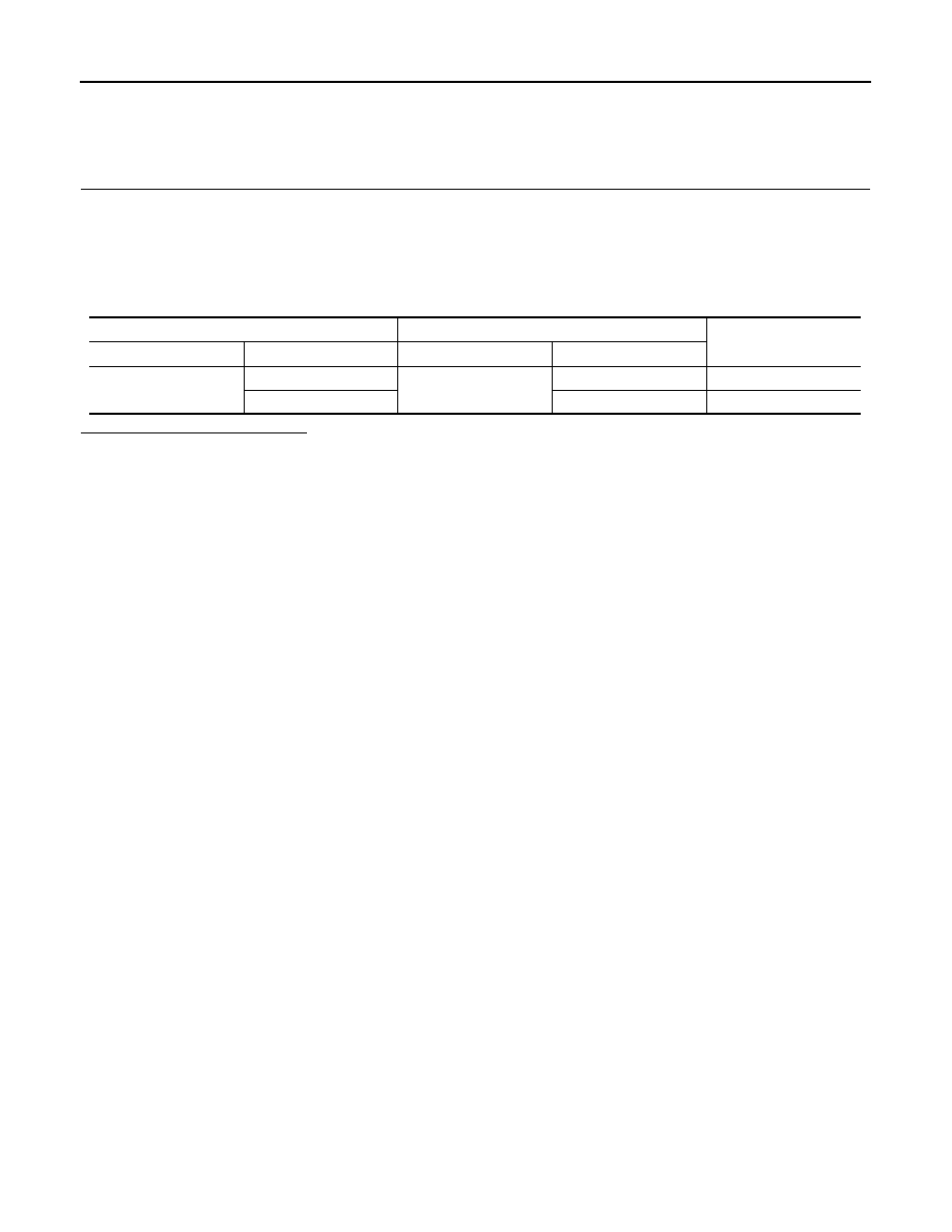
Check the continuity between the combination meter harness connector and the data link connector.

Is the inspection result normal?

YES (Present error)>>Check CAN system type decision again.
YES (Past error)>>Error was detected in the main line between the combination meter and the data link con-

nector. 

NO

>> Repair the main line between the combination meter and the data link connector.

Combination meter harness connector

Data link connector

Continuity

Connector No.

Terminal No.

Connector No.

Terminal No.

M34

21

M4

6

Existed

22

14

Existed

LAN

MAIN LINE BETWEEN DLC AND TCM CIRCUIT

LAN-179

< DTC/CIRCUIT DIAGNOSIS >

[CAN SYSTEM (TYPE 8)]

C

D

E

F

G

H

I

J

K

L

B

A

O

P

N

MAIN LINE BETWEEN DLC AND TCM CIRCUIT

Diagnosis Procedure

INFOID:0000000005595488

1.

CHECK CONNECTOR

1.

Turn the ignition switch OFF.

2.

Disconnect the battery cable from the negative terminal.

3.

Check the following terminals and connectors for damage, bend and loose connection (connector side
and harness side).

-

Harness connector M11

-

Harness connector E105

Is the inspection result normal?

YES

>> GO TO 2.

NO

>> Repair the terminal and connector.

2.

CHECK HARNESS CONTINUITY (OPEN CIRCUIT)

1.

Disconnect the harness connectors M11 and E105.

2.

Check the continuity between the data link connector and the harness connector.

Is the inspection result normal?

YES

>> GO TO 3.

NO

>> Repair the main line between the data link connector and the harness connector M11.

3.

CHECK HARNESS CONTINUITY (OPEN CIRCUIT)

1.

Disconnect the harness connectors E6 and F123.

2.

Check the continuity between the harness connectors.

Is the inspection result normal?

YES (Present error)>>Check CAN system type decision again.
YES (Past error)>>Error was detected in the main line between the data link connector and the TCM. 
NO

>> Repair the main line between the harness connectors E105 and E6.

Data link connector

Harness connector

Continuity

Connector No.

Terminal No.

Connector No.

Terminal No.

M4

6

M11

12

Existed

14

11

Existed

Harness connector

Harness connector

Continuity

Connector No.

Terminal No.

Connector No.

Terminal No.

E105

12

E6

1

Existed

11

8

Existed

LAN-180

< DTC/CIRCUIT DIAGNOSIS >

[CAN SYSTEM (TYPE 8)]

ECM BRANCH LINE CIRCUIT

ECM BRANCH LINE CIRCUIT

Diagnosis Procedure

INFOID:0000000005595489

1.

CHECK CONNECTOR

1.

Turn the ignition switch OFF.

2.

Disconnect the battery cable from the negative terminal.

3.

Check the following terminals and connectors for damage, bend and loose connection (unit side and con-
nector side).

-

Models with automatic back door system

ECM

Harness connector E104

Harness connector B4

-

Models without automatic back door system

ECM

Harness connector E105

Harness connector M11

Is the inspection result normal?

YES

>> GO TO 2.

NO

>> Repair the terminal and connector.

2.

CHECK HARNESS FOR OPEN CIRCUIT

1.

Disconnect the connector of ECM.

2.

Check the resistance between the ECM harness connector terminals.

Is the measurement value within the specification?

YES

>> GO TO 3.

NO

>> Repair the ECM branch line.

3.

CHECK POWER SUPPLY AND GROUND CIRCUIT

Check the power supply and the ground circuit of the ECM. Refer to 

EC-134, "Diagnosis Procedure"

.

Is the inspection result normal?

YES (Present error)>>Replace the ECM. Refer to 

EC-16, "ADDITIONAL SERVICE WHEN REPLACING

CONTROL UNIT : Special Repair Requirement"

.

YES (Past error)>>Error was detected in the ECM branch line.
NO

>> Repair the power supply and the ground circuit.

ECM harness connector

Resistance (

)

Connector No.

Terminal No.

E16

98

97

Approx. 108 – 132

LAN

ADP BRANCH LINE CIRCUIT

LAN-181

< DTC/CIRCUIT DIAGNOSIS >

[CAN SYSTEM (TYPE 8)]

C

D

E

F

G

H

I

J

K

L

B

A

O

P

N

ADP BRANCH LINE CIRCUIT

Diagnosis Procedure

INFOID:0000000005595490

1.

CHECK CONNECTOR

1.

Turn the ignition switch OFF.

2.

Disconnect the battery cable from the negative terminal.

3.

Check the following terminals and connectors for damage, bend and loose connection (unit side and con-
nector side).

-

Driver seat control unit

-

Harness connector B460

-

Harness connector B19

Is the inspection result normal?

YES

>> GO TO 2.

NO

>> Repair the terminal and connector.

2.

CHECK HARNESS FOR OPEN CIRCUIT

1.

Disconnect the connector of driver seat control unit.

2.

Check the resistance between the driver seat control unit harness connector terminals.

Is the measurement value within the specification?

YES

>> GO TO 3.

NO

>> Repair the driver seat control unit branch line.

3.

CHECK POWER SUPPLY AND GROUND CIRCUIT

Check the power supply and the ground circuit of the driver seat control unit. Refer to 

ADP-52, "DRIVER SEAT

CONTROL UNIT : Diagnosis Procedure"

.

Is the inspection result normal?

YES (Present error)>>Replace the driver seat control unit. Refer to 

ADP-209, "Removal and Installation"

.

YES (Past error)>>Error was detected in the driver seat control unit branch line.
NO

>> Repair the power supply and the ground circuit.

Driver seat control unit harness connector

Resistance (

)

Connector No.

Terminal No.

B452

23

24

Approx. 54 – 66


содержание   ..  991  992  993  994   ..