Nissan Murano Z51. Manual - part 952


  Главная      Nissan     Nissan Murano Z51 (2010 year) - Service Manual


поиск по сайту            


содержание   ..  950  951  952  953   ..


Nissan Murano Z51. Manual - part 952


LAN-14

< SYSTEM DESCRIPTION >

[CAN FUNDAMENTAL]

TROUBLE DIAGNOSIS

Self-Diagnosis

INFOID:0000000005594053

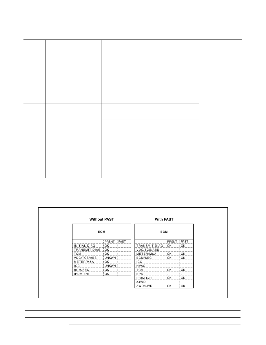
CAN Diagnostic Support Monitor

INFOID:0000000005514792

MONITOR ITEM (CONSULT-III)

Example: CAN DIAG SUPPORT MNTR indication

Without PAST

DTC

Self-diagnosis item

 (CONSULT-III indication)

DTC detection condition

Inspection/Action

U0101

LOST COMM (TCM)

When ECM is not transmitting or receiving CAN communi-
cation signal of OBD (emission-related diagnosis) from 
TCM for 2 seconds or more.

Start the inspection. Re-
fer to the applicable sec-
tion of the indicated 
control unit.

U0140

LOST COMM (BCM)

When ECM is not transmitting or receiving CAN communi-
cation signal of OBD (emission-related diagnosis) from 
BCM for 2 seconds or more.

U0164

LOST COMM (HVAC)

When ECM is not transmitting or receiving CAN communi-
cation signal of OBD (emission-related diagnosis) from A/
C auto amp. or unified meter and A/C amp. for 2 seconds 
or more.

U1000

CAN COMM CIRCUIT

ECM

When ECM is not transmitting or receiving CAN 
communication signal of OBD (emission-relat-
ed diagnosis) for 2 seconds or more.

Except 
for ECM

When a control unit (except for ECM) is not 
transmitting or receiving CAN communication 
signal for 2 seconds or more.

U1001

CAN COMM CIRCUIT

When ECM is not transmitting or receiving CAN communi-
cation signal other than OBD (emission-related diagnosis) 
for 2 seconds or more.

U1002

SYSTEM COMM

When a control unit is not transmitting or receiving CAN 
communication signal for 2 seconds or less.

U1010

CONTROL UNIT(CAN)

When an error is detected during the initial diagnosis for 
CAN controller of each control unit.

Replace the control unit 
indicating “U1010” or 
“P0607”.

P0607

ECM

JSMIA0015GB

Item

PRSNT

Description

Initial diagnosis

OK

Normal at present

NG

Control unit error (Except for some control units)

LAN

TROUBLE DIAGNOSIS

LAN-15

< SYSTEM DESCRIPTION >

[CAN FUNDAMENTAL]

C

D

E

F

G

H

I

J

K

L

B

A

O

P

N

With PAST

MONITOR ITEM (ON-BOARD DIAGNOSIS)

NOTE:
For some models, CAN communication diagnosis result is received from the vehicle monitor.

Example: Vehicle Display 

Transmission diagnosis

OK

Normal at present

UNKWN

Unable to transmit signals for 2 seconds or more.

Diagnosis not performed

Control unit name

(Reception diagnosis)

OK

Normal at present

UNKWN

Unable to receive signals for 2 seconds or more.

Diagnosis not performed

No control unit for receiving signals. (No applicable optional parts)

Item

PRSNT

Description

Item

PRSNT

PAST

Description

Transmission diagnosis

OK

OK

Normal at present and in the past

1 – 39

Normal at present, but unable to transmit signals for 2 seconds or more 
in the past. (The number indicates the number of ignition switch cycles 
from OFF to ON.)

UNKWN

0

Unable to transmit signals for 2 seconds or more at present.

Control unit name

(Reception diagnosis)

OK

OK

Normal at present and in the past

1 – 39

Normal at present, but unable to receive signals for 2 seconds or more 
in the past. (The number indicates the number of ignition switch cycles 
from OFF to ON.)

UNKWN

0

Unable to receive signals for 2 seconds or more at present.

Diagnosis not performed.

No control unit for receiving signals. (No applicable optional parts)

Item

Result indi-

cated

Error counter

Description

CAN_COMM

(Initial diagnosis)

OK

0

Normal at present

NG

1 – 50

Control unit error
(The number indicates how many times diagnosis has been 
run.)

CAN_CIRC_1

(Transmission diagnosis)

OK

0

Normal at present

UNKWN

1 – 50

Unable to transmit for 2 seconds or more at present.
(The number indicates how many times diagnosis has been 
run.)

CAN_CIRC_2 – 9

(Reception diagnosis of each unit)

OK

0

Normal at present

UNKWN

1 – 50

Unable to transmit for 2 seconds or more at present.
(The number indicates how many times diagnosis has been 
run.)

Diagnosis not performed.

No control unit for receiving signals. (No applicable optional 
parts)

LAN-16

< SYSTEM DESCRIPTION >

[CAN FUNDAMENTAL]

TROUBLE DIAGNOSIS

How to Use CAN Communication Signal Chart

INFOID:0000000005514793

The CAN communication signal chart lists the signals needed for trouble diagnosis. It is useful for detecting
the root cause by finding a signal related to the symptom, and by checking transmission and reception unit.

SKIB8715E

LAN

DIAGNOSIS AND REPAIR WORKFLOW

LAN-17

< BASIC INSPECTION >

[CAN FUNDAMENTAL]

C

D

E

F

G

H

I

J

K

L

B

A

O

P

N

BASIC INSPECTION

DIAGNOSIS AND REPAIR WORKFLOW

Trouble Diagnosis Flow Chart

INFOID:0000000005514794

Trouble Diagnosis Procedure

INFOID:0000000005514795

INTERVIEW WITH CUSTOMER

Interview with the customer is important to detect the root cause of CAN communication system errors and to
understand vehicle condition and symptoms for proper trouble diagnosis.

Points in interview

• What: Parts name, system name
• When: Date, Frequency
• Where: Road condition, Place
• In what condition: Driving condition/environment
• Result: Symptom
NOTE:
• Check normal units as well as error symptoms.
- Example: Circuit between ECM and the combination meter is judged normal if the customer indicates

tachometer functions normally.

• When a CAN communication system error is present, multiple control units may malfunction or go into fail-

safe mode.

JSMIA0016GB


содержание   ..  950  951  952  953   ..