содержание .. 914 915 916 917 ..
Nissan Murano Z51. Manual - part 916
BCM (BODY CONTROL MODULE)
INL-65
< ECU DIAGNOSIS INFORMATION >
C
D
E
F
G
H
I
J
K
M
A
B
INL
N
O
P
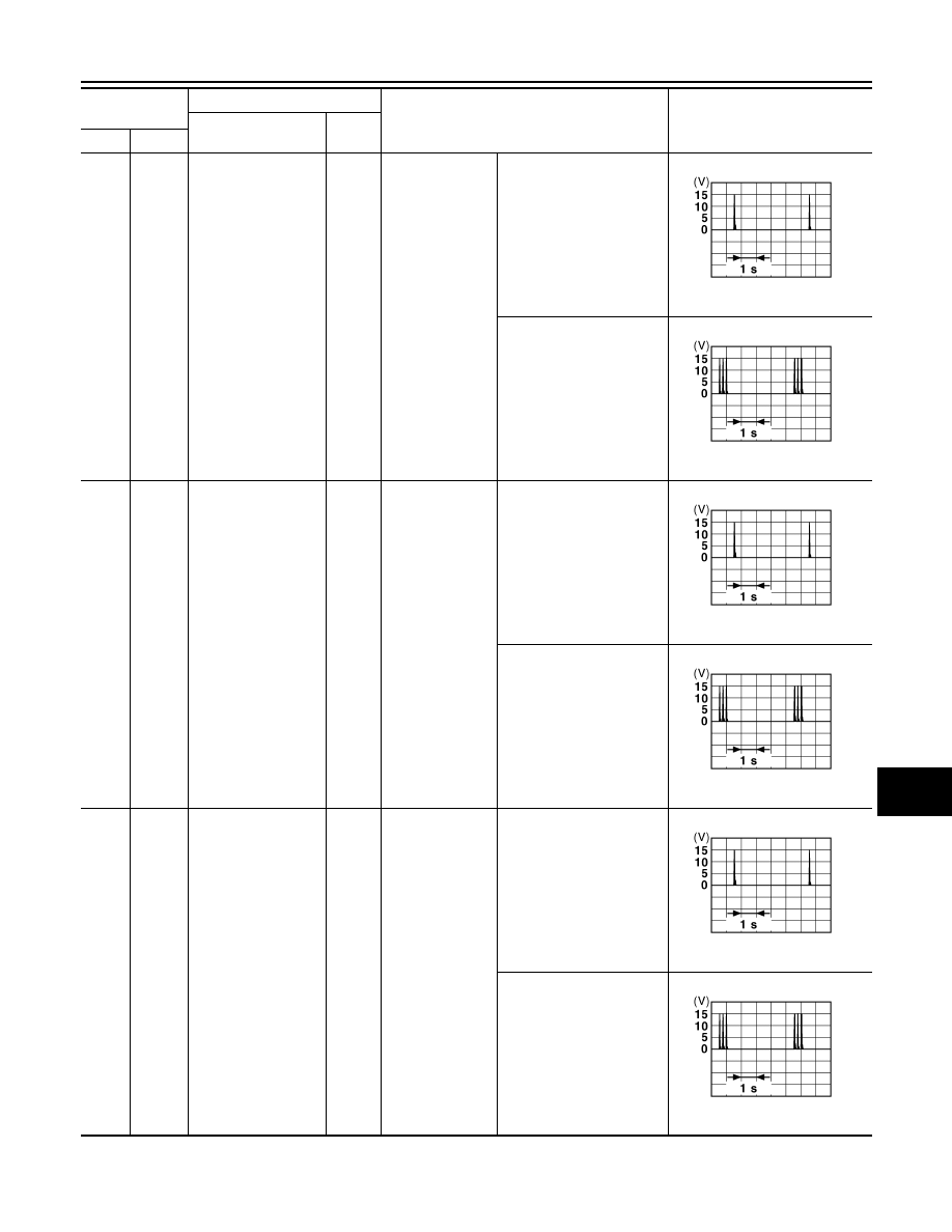
73
(W)
Ground
Room antenna (+)
(Center console)
Output
Ignition switch
OFF
When Intelligent Key is in
the passenger compart-
ment
When Intelligent Key is not
in the passenger compart-
ment
74
(Y)
Ground
Passenger door an-
tenna (-)
Output
When the pas-
senger door re-
quest switch is
operated with ig-
nition switch OFF
When Intelligent Key is in
the antenna detection area
When Intelligent Key is not
in the antenna detection
area
75
(LG)
Ground
Passenger door an-
tenna (+)
Output
When the pas-
senger door re-
quest switch is
operated with ig-
nition switch OFF
When Intelligent Key is in
the antenna detection area
When Intelligent Key is not
in the antenna detection
area
Terminal No.
(Wire color)
Description
Condition
Value
(Approx.)
Signal name
Input/
Output
+
–
JMKIA0062GB
JMKIA0063GB
JMKIA0062GB
JMKIA0063GB
JMKIA0062GB
JMKIA0063GB