содержание .. 848 849 850 851 ..
Nissan Murano Z51. Manual - part 850
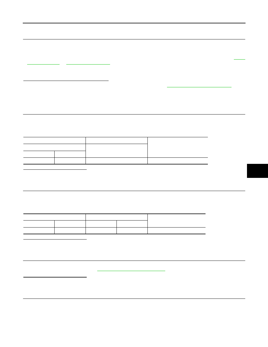
B2630, B2631 SUNLOAD SENSOR
HAC-55
< DTC/CIRCUIT DIAGNOSIS >
[WITHOUT 7 INCH DISPLAY]
C
D
E
F
G
H
J
K
L
M
A
B
HAC
N
O
P
DTC CONFIRMATION PROCEDURE
1.
CHECK WITH SELF-DIAGNOSIS FUNCTION OF CONSULT-III
1.
Using CONSULT-III, perform “SELF-DIAGNOSIS RESULTS” of HVAC.
2.
Check if any DTC No. is displayed in the self-diagnosis results.
NOTE:
• If DTC is displayed along with DTC U1000 or U1010, first diagnose the DTC U1000 or U1010. Refer to
.
• Sunload sensor may register a malfunction when indoors, at dusk, or at other times when light is insufficient.
When performing the diagnosis indoors, light the sunload sensor with a lamp (60W or more).
Is DTC No.“B2630” or “B2631” displayed?
YES
>> Perform trouble diagnosis for the sunload sensor. Refer to
.
NO
>> INSPECTION END
Diagnosis Procedure
INFOID:0000000005514616
1.
CHECK VOLTAGE BETWEEN SUNLOAD SENSOR AND GROUND
1.
Disconnect sunload sensor connector.
2.
Turn ignition switch ON.
3.
Check voltage between sunload sensor harness connector and ground.
Is the inspection result normal?
YES
>> GO TO 2.
NO
>> GO TO 4.
2.
CHECK CIRCUIT CONTINUITY BETWEEN SUNLOAD SENSOR AND A/C AUTO AMP.
1.
Turn ignition switch OFF.
2.
Disconnect A/C auto amp. connector.
3.
Check continuity between sunload sensor harness connector and A/C auto amp. harness connector.
Is the inspection result normal?
YES
>> GO TO 3.
NO
>> Repair harness or connector.
3.
CHECK SUNLOAD SENSOR
1.
Reconnect sunload sensor connector and A/C auto amp. connector.
2.
Check sunload sensor. Refer to
HAC-56, "Component Inspection"
.
Is the inspection result normal?
YES
>> Replace A/C auto amp.
NO
>> Replace sunload sensor.
4.
CHECK CIRCUIT CONTINUITY BETWEEN SUNLOAD SENSOR AND A/C AUTO AMP.
1.
Turn ignition switch OFF.
2.
Disconnect A/C auto amp. connector.
3.
Check continuity between sunload sensor harness connector and A/C auto amp. harness connector.
(+)
(
−
)
Voltage
Sunload sensor
—
Connector
Terminal
M74
1
Ground
Approx. 5 V
Sunload sensor
A/C auto amp.
Continuity
Connector
Terminal
Connector
Terminal
M74
2
M50
37
Existed