Nissan Murano Z51. Manual - part 840


  Главная      Nissan     Nissan Murano Z51 (2010 year) - Service Manual


поиск по сайту            


содержание   ..  838  839  840  841   ..


Nissan Murano Z51. Manual - part 840


AUTOMATIC AIR CONDITIONER SYSTEM

HAC-15

< SYSTEM DESCRIPTION >

[WITHOUT 7 INCH DISPLAY]

C

D

E

F

G

H

J

K

L

M

A

B

HAC

N

O

P

AUTOMATIC AIR CONDITIONER SYSTEM

System Diagram

INFOID:0000000005514578
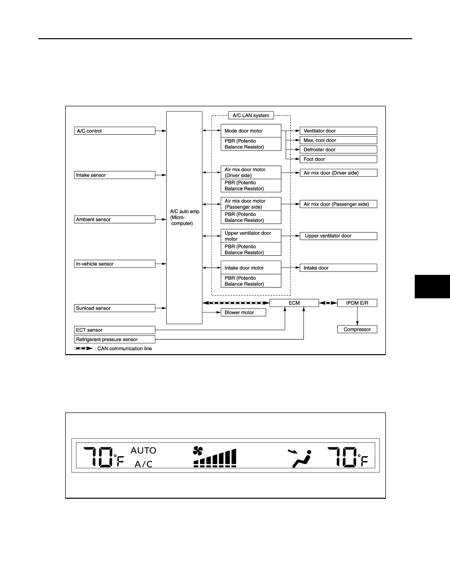
CONTROL SYSTEM

The control system consists of input sensors, switches, the A/C auto amp. (microcomputer) and outputs. The
relationship of these components is as shown in the figure below:

System Description

INFOID:0000000005514579

CONTROL OPERATION

Display

The operation status of the system is displayed on the screen.

JSIIA1539GB

JPIIA0606ZZ

HAC-16

< SYSTEM DESCRIPTION >

[WITHOUT 7 INCH DISPLAY]

AUTOMATIC AIR CONDITIONER SYSTEM

A/C Control

MODE Switch

The air discharge outlets are controlled with this switch.

Temperature Control Switch (Driver Side) 

The set temperature is increased or decreased with this switch.

Temperature Control Switch (Passenger Side) 

• The set temperature is increased or decreased with this switch.
• When this switch is pressed, DUAL switch indicator is turned ON.

AUTO Switch 

• The compressor, intake doors, air mix doors, mode doors and blower speed are automatically controlled so

that the in-vehicle temperature will reach, and be maintained at the set temperature selected by the operator.

• When pressing the AUTO switch, air inlet, air outlet, fan speed, and discharge air temperature are automati-

cally controlled.

Defroster (DEF) Switch

Mode doors are set to the defrost position with this switch. Also, intake doors are set to the outside air position,
and compressor turns ON.

UPPER VENT Switch

• When the UPPER VENT switch is pressed, the UPPER VENT switch indicator is turned ON. 
• When the UPPER VENT switch indicator is turned ON, the UPPER VENT switch indicator is turned OFF by

pressing the defroster (DEF) switch (after the above operation, the UPPER VENT switch indicator is turned
ON by pressing the UPPER VENT switch). 

A/C Switch

Compressor turns ON or OFF with this switch.
(Pressing the A/C switch when the A/C switch is ON turns OFF the A/C switch and compressor.)

Fan Control Dial

The blower speed is manually controlled with this dial. Seven speeds are available for manual control (as
shown on the display screen).

ON/OFF Switch

Compressor and blower turn OFF, air inlet sets to FRE, and mode the position is set to foot position.

Rear Window Defogger Switch

When indicator is ON, rear window is defogged.

Intake Switch

• When the intake switch is ON, the intake switch indicator is turned ON, and air inlet is set to REC.
• When the intake switch is pressed again, the intake switch indicator is turned OFF, and air inlet is set to FRE.
• When the intake switch is pressed for approximately 1.5 seconds or longer, the intake switch indicator blink

twice. Then, automatic control mode is entered. Inlet status is displayed by indicator even when automati-
cally controlled.

JMIIA0485GB

AUTOMATIC AIR CONDITIONER SYSTEM

HAC-17

< SYSTEM DESCRIPTION >

[WITHOUT 7 INCH DISPLAY]

C

D

E

F

G

H

J

K

L

M

A

B

HAC

N

O

P

• When the intake switch indicator is turned OFF, shifting mode position to D/F or DEF, or when compressor is

turned from ON to OFF, intake switch is automatically turned OFF (set to FRE mode). REC mode can be re-
entered by pressing intake switch again, and then compressor is turned ON. (Except D/F or DEF position)

DUAL Switch

• When the DUAL switch indicator is ON, the driver side and passenger side, temperature can each be set

independently.

• When the DUAL switch indicator is OFF, the driver side outlet and setting temperature are applied to both

sides.

HAC-18

< SYSTEM DESCRIPTION >

[WITHOUT 7 INCH DISPLAY]

AUTOMATIC AIR CONDITIONER SYSTEM

DISCHARGE AIR FLOW

JPIIA0512GB


содержание   ..  838  839  840  841   ..