Nissan Murano Z51. Manual - part 836


  Главная      Nissan     Nissan Murano Z51 (2010 year) - Service Manual


поиск по сайту            


содержание   ..  834  835  836  837   ..


Nissan Murano Z51. Manual - part 836


HA-60

< REMOVAL AND INSTALLATION >

EXPANSION VALVE

Removal and Installation

INFOID:0000000005514563

REMOVAL

1.

Use refrigerant collecting equipment (for HFC-134a) to discharge the refrigerant.

2.

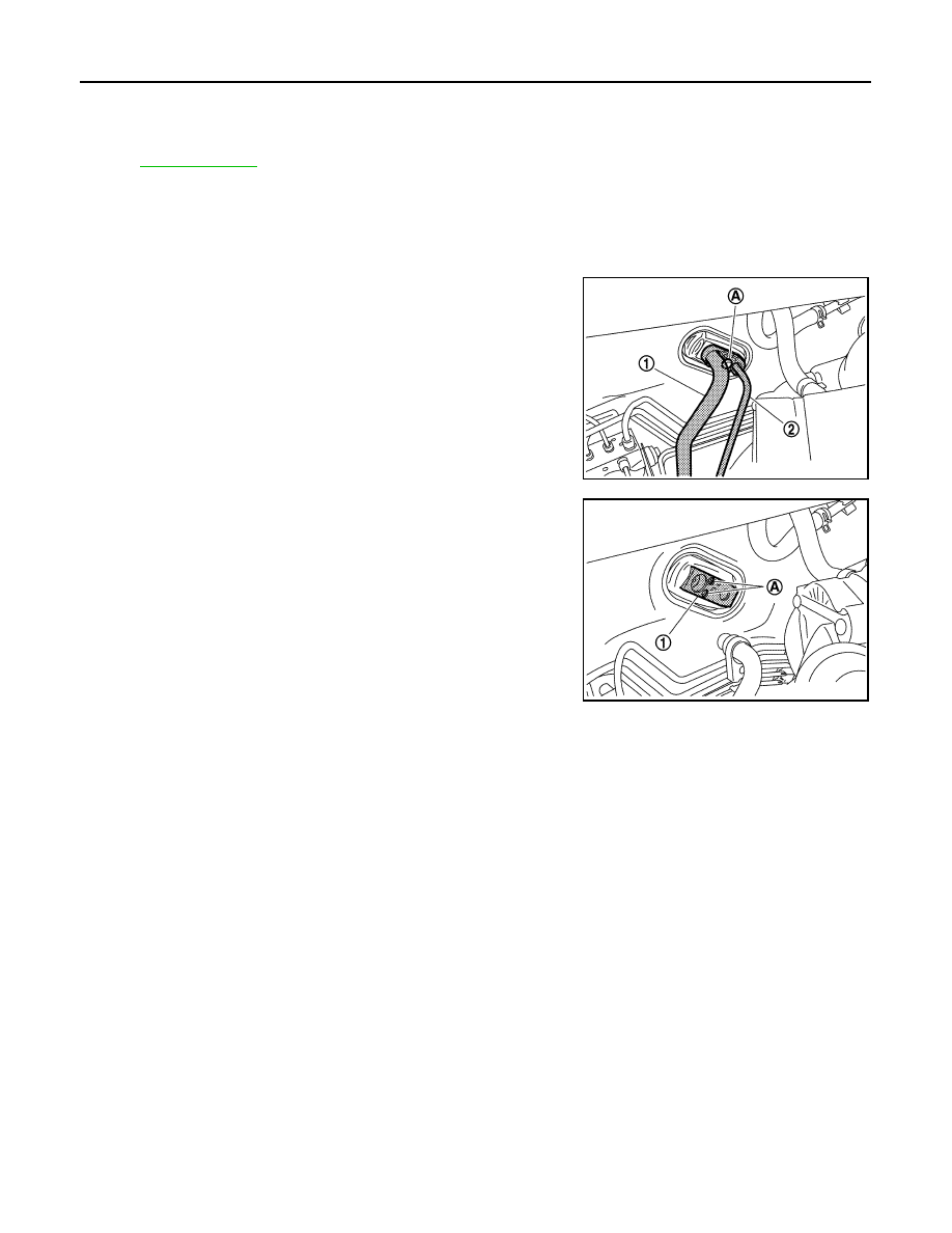
Remove the mounting bolt (A), and then disconnect the low-
pressure pipe (1) and high-pressure pipe (2) from the expansion
valve. 

CAUTION:

Cap or wrap the joint of the A/C piping and expansion valve
with suitable material such as vinyl tape to avoid the entry
of air.

3.

Remove the mounting bolts (A), and then remove the expansion
valve (1). 

CAUTION:

Cap or wrap the joint of the A/C piping and expansion valve
with suitable material such as vinyl tape to avoid the entry
of air.

INSTALLATION

Installation is basically the reverse order of removal.

CAUTION:

• Replace O-rings with new ones. Then apply compressor oil to them when installing. 
• Check for leakages when recharging refrigerant.

49. Air mix door motor (driver side)

50.

Distributor upper case

51.

Distributor lower case

52. Ventilator door

53.

Foot door

54.

Max. cool door

55. Defroster door

56.

Upper ventilator door

Refer to 

GI-4, "Components"

 for symbols in the figure.

JPIIA0561ZZ

JPIIA0549ZZ

SERVICE DATA AND SPECIFICATIONS (SDS)

HA-61

< SERVICE DATA AND SPECIFICATIONS (SDS) 

C

D

E

F

G

H

J

K

L

M

A

B

HA

N

O

P

SERVICE DATA AND SPECIFICATIONS (SDS)

SERVICE DATA AND SPECIFICATIONS (SDS)

Compressor

INFOID:0000000005514564

Lubricant

INFOID:0000000005514565

Refrigerant

INFOID:0000000005514566

Engine Idling Speed

INFOID:0000000005514567

Refer to 

EC-536, "Idle Speed"

.

Belt Tension

INFOID:0000000005514568

Refer to 

EM-145, "Drive Belt"

.

Model

VALEO THERMAL SYSTEMS JAPAN make 

DKS-17D

Type

Fixation displacement swash plate

Displacement

cm

3

 (cu in)/rev

Max.

175 (10.7)

Cylinder bore 

×

 stroke (Max.)

mm (in.)

30.5 (1.20) 

×

 24 (0.94)

Direction of rotation

Clockwise (viewed from clutch)

Drive belt

Poly V

Disc to pulley clearance
mm (in.)

Standard

0.3 - 0.6 (0.012 - 0.024)

Name

NISSAN A/C System Oil Type S (DH-PS)

Capacity

m

 (US fl oz, lmp fl oz)

Total in system

150 (5.07, 5.3)

Compressor (service part) charging 
amount

150 (5.07, 5.3)

Type

HFC-134a (R-134a)

Capacity
kg (lb)

0.60 (1.32)

HAC-1

VENTILATION, HEATER & AIR CONDITIONER

C

D

E

F

G

H

J

K

L

M

SECTION 

HAC

A

B

HAC

N

O

P

CONTENTS

HEATER & AIR CONDITIONING CONTROL SYSTEM

WITHOUT 7 INCH DISPLAY

BASIC INSPECTION  ....................................

5

DIAGNOSIS AND REPAIR WORKFLOW  ..........

5

Work Flow  .................................................................

5

INSPECTION AND ADJUSTMENT .....................

7

Description & Inspection  ...........................................

7

Temperature Setting Trimmer  ...................................

9

Foot Position Setting Trimmer ...................................

9

Inlet Port Memory Function (FRE)  ..........................

10

Inlet Port Memory Function (REC)  ..........................

10

SYSTEM DESCRIPTION  .............................

11

COMPRESSOR CONTROL FUNCTION ............

11

Description ..............................................................

11

Component Part Location  .......................................

12

Component’s Role ...................................................

14

AUTOMATIC AIR CONDITIONER SYSTEM  .....

15

System Diagram ......................................................

15

System Description  .................................................

15

Component Part Location  .......................................

23

Component Description ...........................................

26

MODE DOOR CONTROL SYSTEM  ...................

27

System Diagram ......................................................

27

System Description  .................................................

27

UPPER VENTILATOR DOOR CONTROL 
SYSTEM .............................................................

29

System Diagram ......................................................

29

System Description  .................................................

29

AIR MIX DOOR CONTROL SYSTEM  ................

31

System Diagram ......................................................

31

System Description  .................................................

31

INTAKE DOOR CONTROL SYSTEM  ................

33

System Diagram ......................................................

33

System Description ..................................................

33

BLOWER MOTOR CONTROL SYSTEM  ..........

35

System Diagram  ......................................................

35

System Description ..................................................

35

MAGNET CLUTCH CONTROL SYSTEM  .........

37

System Diagram  ......................................................

37

System Description ..................................................

37

CAN COMMUNICATION SYSTEM  ...................

38

System Description ..................................................

38

DIAGNOSIS SYSTEM (HVAC)  .........................

39

CONSULT-III Function  ............................................

39

DTC/CIRCUIT DIAGNOSIS  .........................

43

U1000 CAN COMM CIRCUIT  ...........................

43

Description ...............................................................

43

DTC Logic ................................................................

43

Diagnosis Procedure ..............................................

43

U1010 CONTROL UNIT (CAN) .........................

44

Description ...............................................................

44

DTC Logic ................................................................

44

Diagnosis Procedure  ...............................................

44

B257B, B257C AMBIENT SENSOR .................

45

Description ...............................................................

45

DTC Logic ................................................................

45

Diagnosis Procedure  ...............................................

46

Component Inspection .............................................

47

B2578, B2579 IN-VEHICLE SENSOR  ..............

48

Description ...............................................................

48

DTC Logic ................................................................

48

Diagnosis Procedure  ...............................................

49

Component Inspection .............................................

50

B2581, B2582 INTAKE SENSOR  .....................

51

Description ...............................................................

51

DTC Logic ................................................................

51

HAC-2

Diagnosis Procedure  ..............................................

51

Component Inspection ............................................

52

B2630, B2631 SUNLOAD SENSOR  .................

54

Description ..............................................................

54

DTC Logic ...............................................................

54

Diagnosis Procedure  ..............................................

55

Component Inspection ............................................

56

B2632, B2633 AIR MIX DOOR MOTOR 
(DRIVER SIDE)  ..................................................

57

Description ..............................................................

57

DTC Logic ...............................................................

57

Diagnosis Procedure  ..............................................

58

B2634, B2635 AIR MIX DOOR MOTOR (PAS-
SENGER SIDE) ..................................................

59

Description ..............................................................

59

DTC Logic ...............................................................

59

Diagnosis Procedure  ..............................................

60

B2636, B2637, B2638, B2639, B2654, B2655 
MODE DOOR MOTOR  ......................................

61

Description ..............................................................

61

DTC Logic ...............................................................

61

Diagnosis Procedure  ..............................................

62

B263D, B263E, B263F INTAKE DOOR MO-
TOR ....................................................................

64

Description ..............................................................

64

DTC Logic ...............................................................

64

Diagnosis Procedure  ..............................................

65

B2661, B2662, B2663 UPPER VENTILATOR 
DOOR MOTOR  ..................................................

66

Description ..............................................................

66

DTC Logic ...............................................................

66

Diagnosis Procedure  ..............................................

67

BLOWER MOTOR  .............................................

69

Description ..............................................................

69

Component Function Check .................................

69

Diagnosis Procedure  ..............................................

69

Component Inspection ............................................

72

MAGNET CLUTCH  ............................................

73

Description ..............................................................

73

Component Function Check  ...................................

73

Diagnosis Procedure  ..............................................

73

A/C CONTROL SIGNAL CIRCUIT  ....................

75

Diagnosis Procedure  ..............................................

75

POWER SUPPLY AND GROUND CIRCUIT  .....

76

A/C AUTO AMP.  .......................................................

76

A/C AUTO AMP. : Description  ................................

76

A/C AUTO AMP. : Component Function Check  .....

76

A/C AUTO AMP. : Diagnosis Procedure  ................

76

A/C CONTROL ..........................................................

77

A/C CONTROL : Diagnosis Procedure  ...................

77

A/C DISPLAY  ............................................................

78

A/C DISPLAY : Diagnosis Procedure  .....................

78

ECU DIAGNOSIS INFORMATION .............

79

ECM ...................................................................

79

Reference Value  .....................................................

79

A/C AUTO AMP. ................................................

94

Reference Value  .....................................................

94

Wiring Diagram - AIR CONDITIONER CONTROL 
SYSTEM -  ...............................................................

96

Fail-Safe ................................................................

105

DTC Inspection Priority Chart .............................

106

DTC Index .............................................................

106

SYMPTOM DIAGNOSIS  ...........................

108

AIR CONDITIONER CONTROL  .......................

108

Diagnosis Chart By Symptom  ...............................

108

INSUFFICIENT COOLING ................................

109

Description ............................................................

109

Inspection procedure  ............................................

109

INSUFFICIENT HEATING  ................................

112

Description ............................................................

112

Inspection procedure  ............................................

112

NOISE ...............................................................

115

Description ............................................................

115

Inspection procedure  ............................................

115

MEMORY FUNCTION DOES NOT OPERATE ..

117

Description ............................................................

117

Inspection procedure  ............................................

117

PRECAUTION ...........................................

118

PRECAUTIONS  ................................................

118

FOR USA AND CANADA  .......................................

118

FOR USA AND CANADA : Precaution for Supple-
mental Restraint System (SRS) "AIR BAG" and 
"SEAT BELT PRE-TENSIONER"  .........................

118

FOR MEXICO  ..........................................................

118

FOR MEXICO : Precaution for Supplemental Re-
straint System (SRS) "AIR BAG" and "SEAT BELT 
PRE-TENSIONER" ...............................................

118

Precaution Necessary for Steering Wheel Rota-
tion after Battery Disconnect .................................

119

Precaution for Procedure without Cowl Top Cover .

119

Precautions For Xenon Headlamp Service ...........

119

Working with HFC-134a (R-134a) .........................

120

General Refrigerant Precaution  ............................

120

Refrigerant Connection  .........................................

121

Service Equipment ................................................

123

COMPRESSOR  ................................................

125


содержание   ..  834  835  836  837   ..