содержание .. 784 785 786 787 ..
Nissan Murano Z51. Manual - part 786
FRONT WHEEL HUB AND KNUCKLE
FAX-37
< REMOVAL AND INSTALLATION >
[AWD]
C
E
F
G
H
I
J
K
L
M
A
B
FAX
N
O
P
REMOVAL AND INSTALLATION
FRONT WHEEL HUB AND KNUCKLE
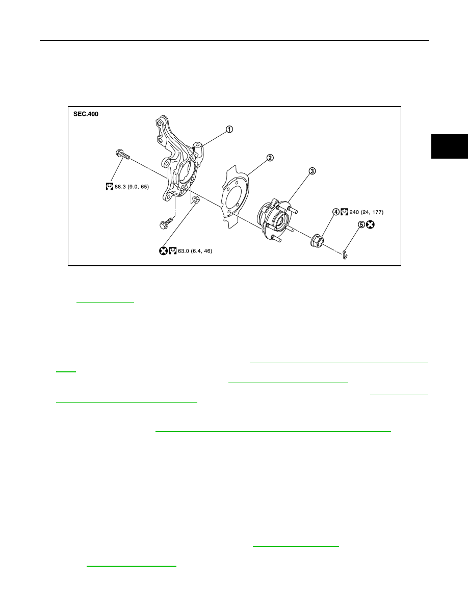
Exploded View
INFOID:0000000005518976
Removal and Installation
INFOID:0000000005518977
REMOVAL
1.
Remove tires with power tool.
2.
Remove wheel sensor and sensor harness. Refer to
BRC-110, "FRONT WHEEL SENSOR : Exploded
.
3.
Remove lock plate from strut assembly. Refer to
BR-22, "FRONT : Exploded View"
.
4.
Remove caliper assembly. Hang caliper assembly not to interfere with work. Refer to
CALIPER ASSEMBLY : Exploded View"
.
CAUTION:
Never depress brake pedal while brake caliper is removed.
5.
Remove disc rotor. Refer to
BR-37, "BRAKE CALIPER ASSEMBLY : Removal and Installation"
.
6.
Remove cotter pin, and then loosen wheel hub lock nut with power tool.
7.
Patch wheel hub lock nut with a piece of wood. Hammer the wood to disengage wheel hub and bearing
assembly from drive shaft.
CAUTION:
• Never place drive shaft joint at an extreme angle. Also be careful not to overextend slide joint.
• Never allow drive shaft to hang down without support for joint sub-assembly, shaft and the other
parts.
NOTE:
Use suitable puller, if wheel hub and bearing assembly and drive shaft cannot be separated even after
performing the above procedure.
8.
Remove wheel hub lock nut.
9.
Remove strut assembly from steering knuckle. Refer to
.
10. Remove drive shaft from wheel hub and bearing assembly, suspend the drive shaft with suitable wire.
11. Temporarily tighten strut assembly and steering knuckle.
1.
Steering knuckle
2.
Splash guard
3.
Wheel hub and bearing assembly
4.
Wheel hub lock nut
5.
Cotter pin
Refer to
JPDIF0274GB