содержание .. 713 714 715 716 ..
Nissan Murano Z51. Manual - part 715
BOTH SIDE FRONT FOG LAMPS ARE NOT TURNED ON
EXL-171
< SYMPTOM DIAGNOSIS >
[XENON TYPE]
C
D
E
F
G
H
I
J
K
M
A
B
EXL
N
O
P
BOTH SIDE FRONT FOG LAMPS ARE NOT TURNED ON
Description
INFOID:0000000005515096
The front fog lamps are not turned ON in any condition.
Diagnosis Procedure
INFOID:0000000005515097
1.
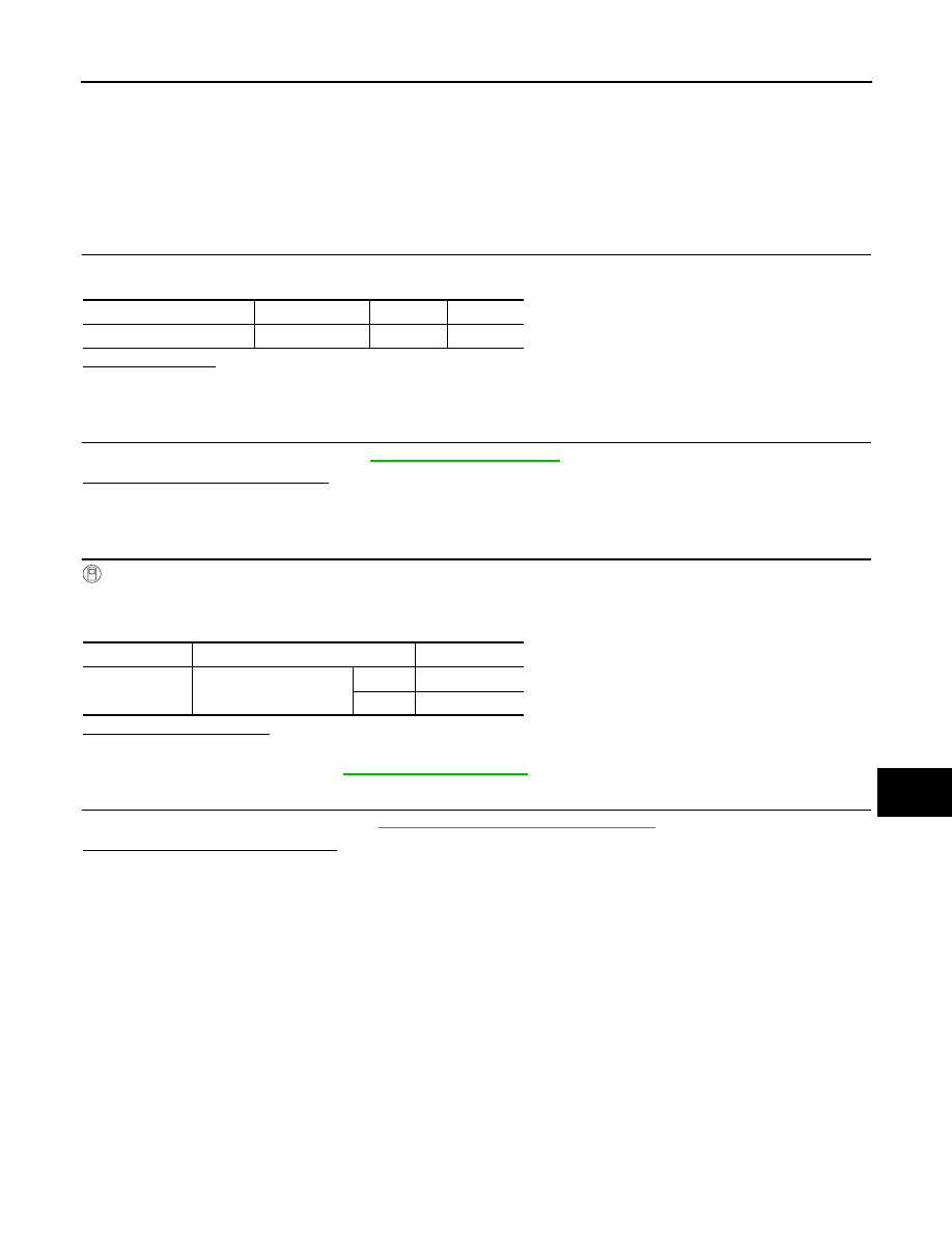
CHECK FUSE
Check that the following fuse is fusing.
Is the fuse fusing?
YES
>> Repair the applicable circuit. And then replace the fuse.
NO
>> GO TO 2.
2.
COMBINATION SWITCH INSPECTION
Check the combination switch. Refer to
Is the combination switch normal?
YES
>> GO TO 3.
NO
>> Repair or replace the malfunctioning part.
3.
CHECK FRONT FOG LAMP REQUEST SIGNAL INPUT
CONSULT-III DATA MONITOR
1.
Select “FR FOG REQ” of IPDM E/R data monitor item.
2.
With operating the front fog lamp switch, check the monitor status.
Is the item status normal?
YES
>> GO TO 4.
NO
>> Replace BCM. Refer to
.
4.
FRONT FOG LAMP CIRCUIT INSPECTION
Check the front fog lamp circuit. Refer to
EXL-43, "Component Function Check"
.
Is the front fog lamp circuit normal?
YES
>> Replace IPDM E/R.
NO
>> Repair or replace the malfunctioning part.
Unit
Location
Fuse No.
Capacity
Front fog lamp
IPDM E/R
#58
15 A
Monitor item
Condition
Monitor status
FR FOG REQ
Front fog lamp switch
(With lighting switch 1ST)
ON
On
OFF
Off