Nissan Murano Z51. Manual - part 685


  Главная      Nissan     Nissan Murano Z51 (2010 year) - Service Manual


поиск по сайту            


содержание   ..  683  684  685  686   ..


Nissan Murano Z51. Manual - part 685


TURN SIGNAL LAMP CIRCUIT

EXL-51

< DTC/CIRCUIT DIAGNOSIS >

[XENON TYPE]

C

D

E

F

G

H

I

J

K

M

A

B

EXL

N

O

P

Does continuity exist?

YES

>> Repair the harnesses or connectors.

NO

>> GO TO 5.

5.

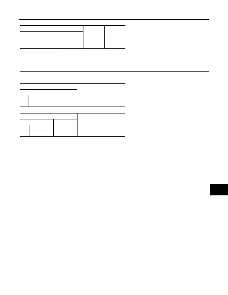
CHECK TURN SIGNAL LAMP GROUND OPEN CIRCUIT

Check continuity between the front turn signal lamp or the rear combination lamp and the ground.

Front turn signal lamp

Rear turn signal lamp

Does continuity exist?

YES

>> Replace the front combination lamp or the rear combination lamp.

NO

>> Repair the harnesses or connectors.

BCM

Ground

Continuity

Connector

Terminal

RH

M119

17

Not existed

LH

18

Front turn signal lamp

Ground

Continuity

Connector

Terminal

RH

E328

2

Existed

LH

E327

Rear combination lamp

Ground

Continuity

Connector

Terminal

RH

B59

1

Existed

LH

B80

EXL-52

< DTC/CIRCUIT DIAGNOSIS >

[XENON TYPE]

OPTICAL SENSOR

OPTICAL SENSOR

Description

INFOID:0000000005515059

Optical sensor converts the outside brightness (lux) to voltage and transmits the optical sensor signal to BCM.

Component Function Check

INFOID:0000000005515060

1.

CHECK OPTICAL SENSOR SIGNAL BY CONSULT-III

CONSULT-III DATA MONITOR

1.

Turn the ignition switch ON.

2.

Select "OPTICAL SENSOR" of BCM (HEADLAMP) data monitor item.

3.

Turn the lighting switch AUTO.

4.

With the optical sensor illuminating, check the monitor status. 

*: Illuminates the optical sensor. The value may be less than the standard value if brightness is weak.

Is the item status normal?

YES

>> Optical sensor is normal.

NO

>> Refer to 

EXL-52, "Diagnosis Procedure"

.

Diagnosis Procedure

INFOID:0000000005515061

1.

CHECK OPTICAL SENSOR POWER SUPPLY INPUT

1.

Turn the ignition switch ON.

2.

Turn the lighting switch AUTO.

3.

Check the voltage between the optical sensor harness connector and the ground.

Is the measurement value normal?

YES

>> GO TO 2.

NO

>> GO TO 4.

2.

CHECK OPTICAL SENSOR GROUND INPUT

Check the voltage between the optical sensor harness connector and the ground.

Is the measurement value normal?

YES

>> GO TO 3.

NO

>> GO TO 6.

Monitor item

Condition

Voltage (Approx.)

OPTICAL SEN-
SOR

Optical sensor

When illuminat-
ing

3.1 V or more *

When shutting 
off light

0.6 V or less

Terminals

Voltage

(Approx.)

(+)

(

)

Optical sensor

Ground

Connector

Terminal

M17

1

5 V

Terminals

Voltage

(Approx.)

(+)

(

)

Optical sensor

Ground

Connector

Terminal

M17

3

0 V

OPTICAL SENSOR

EXL-53

< DTC/CIRCUIT DIAGNOSIS >

[XENON TYPE]

C

D

E

F

G

H

I

J

K

M

A

B

EXL

N

O

P

3.

CHECK OPTICAL SENSOR SIGNAL OUTPUT

 With illuminating the optical sensor, check the voltage between the optical sensor harness connector and the
ground.

*: Illuminate the optical sensor. The value may be less than the standard if brightness is weak.

Is the measurement value normal?

YES

>> GO TO 7.

NO

>> Replace the optical sensor.

4.

CHECK OPTICAL SENSOR OPEN CIRCUIT

1.

Turn the ignition switch OFF.

2.

Disconnect the optical sensor connector and BCM connector.

3.

Check continuity between the optical sensor harness connector and the BCM harness connector.

Does continuity exist?

YES

>> GO TO 5.

NO

>> Repair the harnesses or connectors.

5.

CHECK OPTICAL SENSOR SHORT CIRCUIT

Check the continuity between the optical sensor harness connector and the ground.

Does continuity exist?

YES

>> Repair the harnesses or connectors.

NO

>> Replace BCM.

6.

CHECK OPTICAL SENSOR GROUND OPEN CIRCUIT

1.

Turn the ignition switch OFF.

2.

Disconnect the optical sensor connector and BCM connector.

3.

Check continuity between the optical sensor harness connector and the BCM harness connector.

Does continuity exist?

YES

>> Replace BCM.

NO

>> Repair the harnesses or connectors.

7.

CHECK OPTICAL SENSOR SIGNAL OPEN CIRCUIT 

Terminals

Condition

Voltage

(Approx.)

(+)

(

)

Optical sensor

Ground

Optical sen-

sor

Connector

Terminal

M17

2

When illumi-
nating

3.1 V or 
more *

When shut-
ting off light

0.6 V or less

Optical sensor

BCM

Continuity

Connector

Terminal

Connector

Terminal

M17

1

M123

138

Existed

Optical sensor

Ground

Continuity

Connector

Terminal

M17

1

Not existed

Optical sensor

BCM

Continuity

Connector

Terminal

Connector

Terminal

M17

3

M123

137

Existed

EXL-54

< DTC/CIRCUIT DIAGNOSIS >

[XENON TYPE]

OPTICAL SENSOR

1.

Turn the ignition switch OFF.

2.

Disconnect the optical sensor connector and BCM connector.

3.

Check continuity between the optical sensor harness connector and the BCM harness connector.

Does continuity exist?

YES

>> GO TO 8.

NO

>> Repair the harnesses or connectors.

8.

CHECK OPTICAL SENSOR SHORT CIRCUIT

Check the continuity between the optical sensor harness connector and the ground.

Does continuity exist?

YES

>> Repair the harnesses or connectors.

NO

>> Replace BCM.

Optical sensor

BCM

Continuity

Connector

Terminal

Connector

Terminal

M17

2

M123

113

Existed

Optical sensor

Ground

Continuity

Connector

Terminal

M17

2

Not existed


содержание   ..  683  684  685  686   ..