Nissan Murano Z51. Manual - part 643


  Главная      Nissan     Nissan Murano Z51 (2010 year) - Service Manual


поиск по сайту            


содержание   ..  641  642  643  644   ..


Nissan Murano Z51. Manual - part 643


EM-44

< REMOVAL AND INSTALLATION >

OIL PAN AND OIL STRAINER

• Splash guard (RH and LH): Refer to 

EXT-24, "FENDER PROTECTOR : Exploded View"

.

• Exhaust front tube: Refer to 

EX-5, "Exploded View"

.

• Drive belt: Refer to 

EM-17, "Removal and Installation"

.

4.

Remove A/C compressor with piping connected, and temporarily secure it to aside. Refer to 

HA-37,

"Exploded View"

.

5.

Remove oil level gauge. Refer to 

EM-110, "Exploded View"

.

6.

Remove front drive shaft (RH). Refer to 

FAX-17, "Exploded View"

 (2WD models) or 

FAX-44, "Exploded

View"

 (AWD models).

7.

Remove three way catalyst (bank 1 and bank 2) from exhaust manifolds (bank 1 and bank 2). Refer to

EM-38, "Exploded View"

.

8.

Remove oil pressure switch.

9.

Remove oil filter. Refer to 

LU-10, "Removal and Installation"

.

10. Remove oil cooler and water pipes. Refer to 

LU-11, "Exploded View"

.

11. Support transaxle assembly with a suitable jack.

CAUTION:

When setting the transmission jack, be careful not to allow it to collide against the drain plug.

12. Support front suspension member with a suitable jack.

13. Remove engine mounting insulator (rear). Refer to 

EM-72, "2WD : Exploded View"

 (2WD models) or 

EM-

81, "AWD : Exploded View"

 (AWD models).

14. Remove engine mounting insulator (LH) mounting bolts from transaxle. Refer to 

EM-72, "2WD : Exploded

View"

 (2WD models) or 

EM-81, "AWD : Exploded View"

 (AWD models).

15. Remove rear torque rod through bolts from rear torque rod bracket. Refer to 

EM-72, "2WD : Exploded

View"

 (2WD models) or 

EM-81, "AWD : Exploded View"

 (AWD models).

16. Remove member stay, front suspension member fixing bolts and nuts. Refer to 

FSU-16, "Exploded View"

.

17. Lower the jack for the front suspension member to the height.

18. Remove transfer assembly. Refer to 

DLN-54, "Exploded View"

 (AWD models).

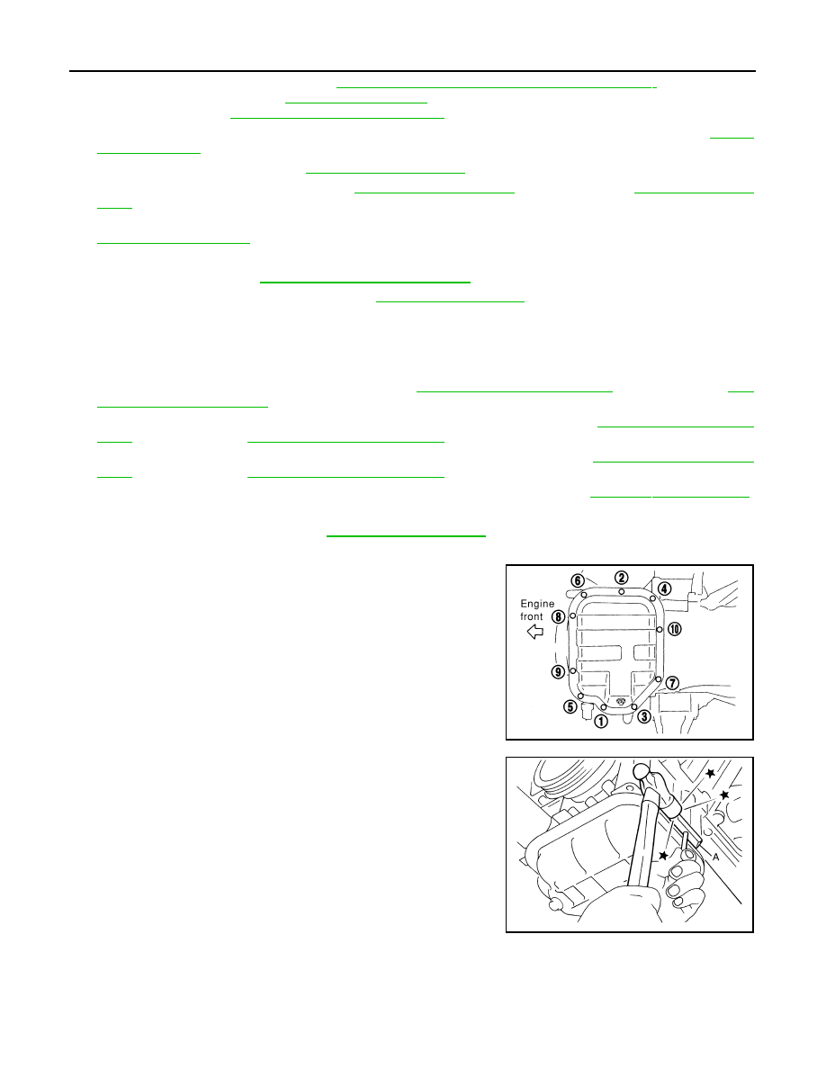
19. Remove oil pan (lower) as follows:
a.

Loosen mounting bolts in the reverse order as shown in the fig-
ure to remove.

b.

Insert the seal cutter [SST: KV10111100 (J-37228)] (A) between
oil pan (upper) and oil pan (lower).

CAUTION:

• Be careful not to damage the mating surfaces.
• Never insert a screwdriver, this will damage the mating

surfaces.

c.

Slide the seal cutter by tapping on the side of tool with a ham-
mer. Remove oil pan (lower).

20. Remove oil strainer.

PBIC0782E

JPBIA0276ZZ

OIL PAN AND OIL STRAINER

EM-45

< REMOVAL AND INSTALLATION >

C

D

E

F

G

H

I

J

K

L

M

A

EM

N

P

O

21. Loosen mounting bolts in the reverse order as shown in the fig-

ure to remove.
• Insert the seal cutter [SST: KV10111100 (J-37228)] between

oil pan (upper) and cylinder block. Slide seal cutter by tapping
on the side of tool with a hammer. Remove oil pan (upper).

CAUTION:

• Be careful not to damage the mating surfaces.
• Never insert a screwdriver, this will damage the mating

surfaces.

22. Remove O-rings (2) from bottom of cylinder block (1) and oil

pump (3).

23. Remove oil pan gaskets (1).

INSTALLATION

1.

Install oil pan (upper) as follows:

a.

Use a scraper to remove old liquid gasket from mating surfaces.

CAUTION:

Never scratch or damage the mating surfaces when clean-
ing off old liquid gasket.
• Also remove old liquid gasket from mating surface of cylinder

block.

• Remove old liquid gasket from the bolt holes and threads.

b.

Install new oil pan gaskets.

PBIC1636E

: Engine front

JPBIA1379ZZ

A

: Notch

B

:  Protrusion

: Engine front

JPBIA0433ZZ

MEM108A

EM-46

< REMOVAL AND INSTALLATION >

OIL PAN AND OIL STRAINER

• Apply liquid gasket to new oil pan gaskets as shown in the fig-

ure.

Use Genuine RTV Silicone Sealant or equivalent. Refer to

GI-18, "Recommended Chemical Products and Sealants"

.

• To install, align protrusion (B) of oil pan gasket with notches

(A) of front timing chain case and rear oil seal retainer.

• Install oil pan gasket (1) with smaller arc to front timing chain

case side.

c.

Install new O-rings (2) on the bottom of cylinder block (1) and oil
pump (3).

d.

Apply a continuous bead of liquid gasket with the tube presser
(commercial service tool) to the cylinder block mating surface of
oil pan (upper) to a limited portion as shown in the figure.

Use Genuine RTV Silicone Sealant or equivalent. Refer to

GI-18, "Recommended Chemical Products and Sealants"

.

CAUTION:

• For bolt holes with   marks (5 locations), apply liquid

gasket outside the holes.

• Apply a bead of 4.5 to 5.5 mm (0.177 to 0.217 in) diameter to area (a).
• Attaching should be done within 5 minutes after coating.

e.

Install oil pan (upper).

CAUTION:

Install avoiding misalignment of both O-rings.

C

: Sealing point

a

: 15 mm (0.59 in)

b

: 5 mm (0.20 in)

JPBIA0432ZZ

: Engine front

JPBIA0433ZZ

: Engine front

JPBIA1379ZZ

b

: 35 mm (1.38 in)

c

φ

3.5 - 4.5 mm (0.138 - 0.177 in)

: Engine front

JPBIA0434ZZ

OIL PAN AND OIL STRAINER

EM-47

< REMOVAL AND INSTALLATION >

C

D

E

F

G

H

I

J

K

L

M

A

EM

N

P

O

• Tighten mounting bolts in numerical order as shown in the fig-

ure.

• There are three types of mounting bolts. Refer to the following

for locating bolts.

2.

Install oil strainer to oil pump.

3.

Install oil pan (lower) as follows:

a.

Use scraper (A) to remove old liquid gasket from mating sur-
faces.
• Remove old liquid gasket from the bolt holes and thread.

CAUTION:

Never scratch or damage the mating surfaces when clean-
ing off old liquid gasket.

b.

Apply a continuous bead of liquid gasket with the tube presser
(commercial service tool) (A) to the oil pan (lower) as shown in
the figure.

Use Genuine RTV Silicone Sealant or equivalent. Refer to

GI-18, "Recommended Chemical Products and Sealants"

.

CAUTION:

Attaching should be done within 5 minutes after coating.

c.

Install oil pan (lower).
• Tighten mounting bolts in numerical order as shown in the fig-

ure.

4.

Install oil pan drain plug.
• Refer to the figure of components of former page for installa-

tion direction of drain plug washer. Refer to 

EM-43, "Exploded

View"

.

5.

Install in the reverse order of removal after this step.
NOTE:
At least 30 minutes after oil pan is installed, pour engine oil.

Inspection

INFOID:0000000005515941

INSPECTION AFTER REMOVAL

Clean oil strainer if any object attached.

INSPECTION AFTER INSTALLATION

1.

Check the engine oil level and adjust engine oil. Refer to 

LU-7, "Inspection"

.

2.

Start engine, and check there is no leakage of engine oil.

M8 

×

 135 mm (5.31 in)

: 11

M8 

×

 92 mm (3.62 in)

: 5, 7, 8

M8 

×

 25 mm (0.98 in)

: Except the above

PBIC1636E

JPBIA0025ZZ

b

φ

4.0 - 5.0 mm (0.157 - 0.197 in)

JPBIA0026ZZ

PBIC0782E


содержание   ..  641  642  643  644   ..