содержание .. 635 636 637 638 ..
Nissan Murano Z51. Manual - part 637
EM-20
< PERIODIC MAINTENANCE >
SPARK PLUG
SPARK PLUG
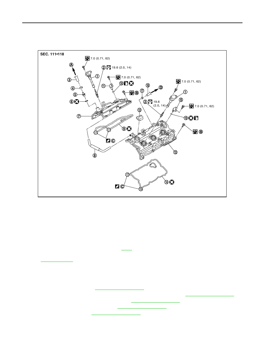
Exploded View
INFOID:0000000005515919
Removal and Installation
INFOID:0000000005515920
REMOVAL
1.
Remove engine cover. Refer to
2.
Remove air cleaner cases (upper and lower) and air duct assembly. Refer to
.
3.
Remove electric throttle control actuator. Refer to
.
4.
Remove intake manifold collector. Refer to
5.
Remove ignition coil. Refer to
.
1.
Ignition coil
2.
Spark plug
3.
PCV hose
4.
Clamp
5.
PCV valve
6.
O-ring
7.
Rocker cover (bank 1)
8.
PCV hose
9.
Rocker cover gasket (bank 1)
10.
O-ring
11.
Camshaft position sensor (PHASE)
(bank 1)
12. Oil filler cap
13.
Rocker cover (bank 2)
14.
Rocker cover gasket (bank 2)
15.
Camshaft position sensor (PHASE)
(bank 2)
16.
PCV hose
17.
Clamp
A.
To intake manifold collector
B.
Refer to
C.
Camshaft bracket side
D.
To air duct
Refer to
for symbols in the figure.
JPBIA1637GB