содержание .. 629 630 631 632 ..
Nissan Murano Z51. Manual - part 631
EC-532
< PERIODIC MAINTENANCE >
[VQ35DE]
EVAP LEAK CHECK
EVAP LEAK CHECK
Inspection
INFOID:0000000005536915
CAUTION:
• Never use compressed air or a high pressure pump.
• Never exceed 4.12 kPa (0.042 kg/cm
2
, 0.6 psi) of pressure in EVAP system.
NOTE:
• Do not start engine.
• Improper installation of EVAP service port adapter (commercial service tool) to the EVAP service port may
cause a leakage.
WITH CONSULT-III
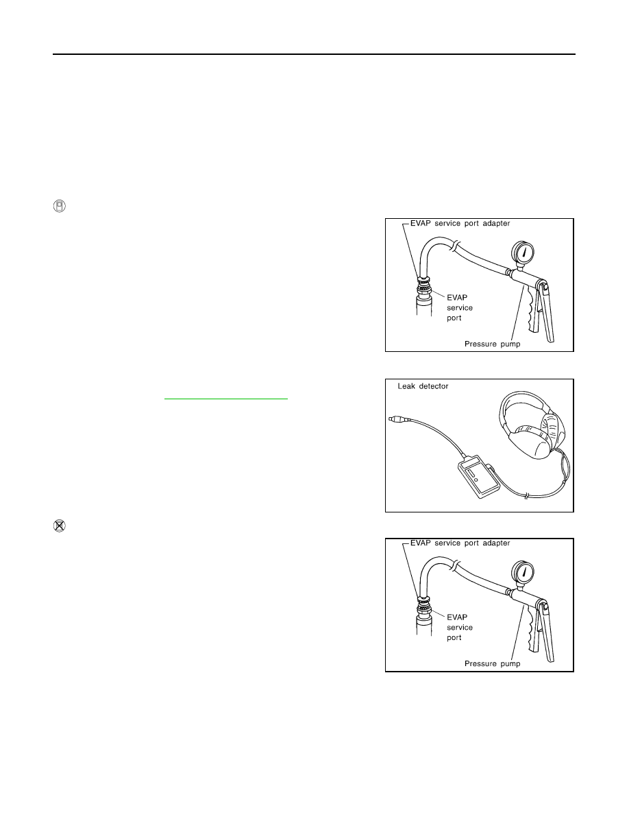
1.
To locate the EVAP leakage, install EVAP service port adapter
(commercial service tool) and pressure pump to EVAP service
port.
2.
Turn ignition switch ON.
3.
Select the “EVAP SYSTEM CLOSE” of “WORK SUPPORT
MODE” with CONSULT-III.
4.
Touch “START”. A bar graph (Pressure indicating display) will
appear on the screen.
5.
Apply positive pressure to the EVAP system until the pressure
indicator reaches the middle of the bar graph.
6.
Remove EVAP service port adapter (commercial service tool)
and hose with pressure pump.
7.
Locate the leakage using a leakage detector (commercial ser-
vice tool). Refer to
.
WITHOUT CONSULT-III
1.
To locate the EVAP leakage, install EVAP service port adapter
(commercial service tool) and pressure pump to EVAP service
port.
2.
Apply battery voltage between the terminals of EVAP canister
vent control valve to make a closed EVAP system.
3.
To locate the leakage, deliver positive pressure to the EVAP sys-
tem until pressure gauge points reach 1.38 to 2.76 kPa (0.014 to
0.028 kg/cm
2
, 0.2 to 0.4 psi).
4.
Remove EVAP service port adapter (commercial service tool)
and hose with pressure pump.
SEF462UA
SEF200U
SEF462UA