Nissan Murano Z51. Manual - part 539


  Главная      Nissan     Nissan Murano Z51 (2010 year) - Service Manual


поиск по сайту            


содержание   ..  537  538  539  540   ..


Nissan Murano Z51. Manual - part 539


EC-164

< DTC/CIRCUIT DIAGNOSIS >

[VQ35DE]

P0112, P0113 IAT SENSOR

P0112, P0113 IAT SENSOR

Description

INFOID:0000000005536566

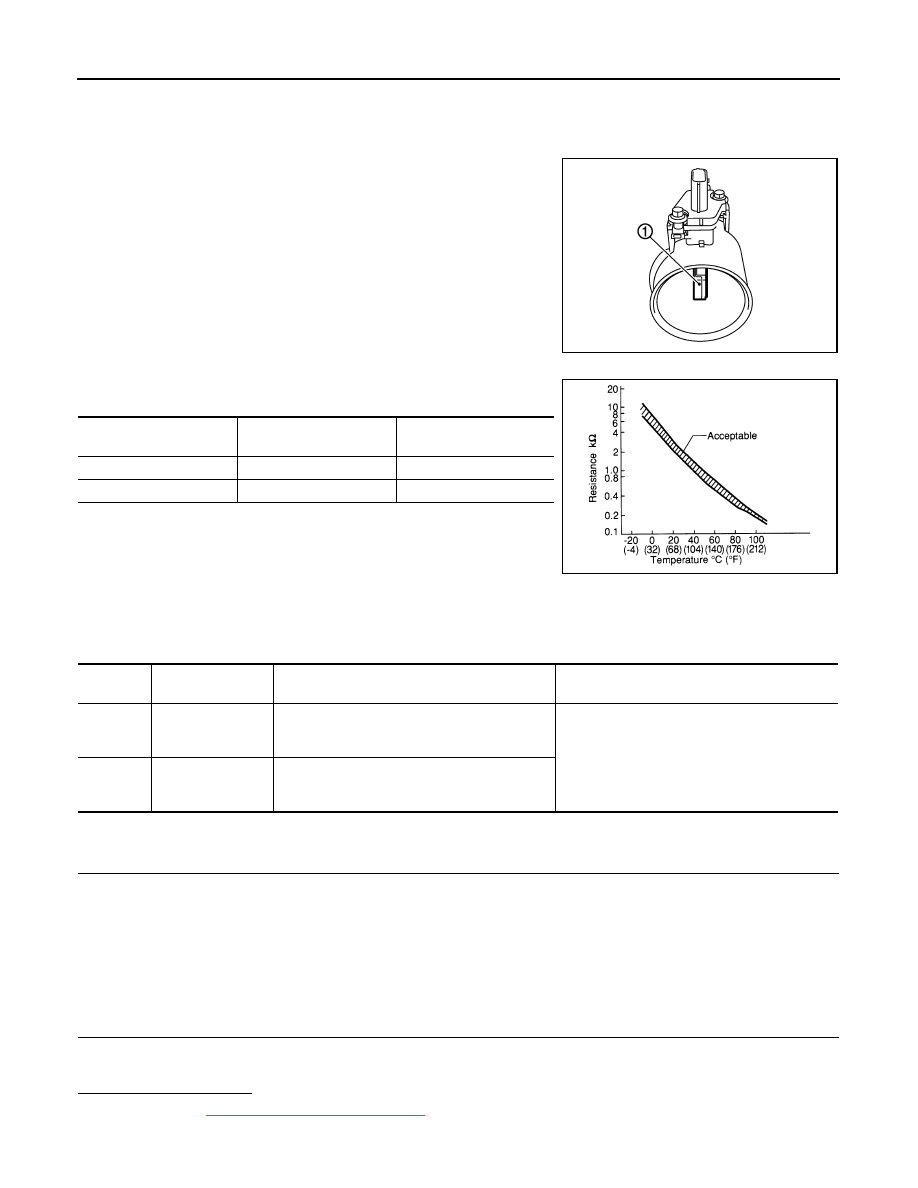
The intake air temperature sensor is built-into the mass air flow sen-
sor (1). The sensor detects intake air temperature and transmits a
signal to the ECM.
The temperature sensing unit uses a thermistor which is sensitive to
the change in temperature. Electrical resistance of the thermistor
decreases in response to the rise in temperature.

<Reference data>

*: These data are reference values and are measured between ECM terminals 50
(Intake air temperature sensor) and 56 (Sensor ground).

DTC Logic

INFOID:0000000005536567

DTC DETECTION LOGIC

DTC CONFIRMATION PROCEDURE

1.

PRECONDITIONING

If DTC Confirmation Procedure has been previously conducted, always perform the following before conduct-
ing the next test.
1.

Turn ignition switch OFF and wait at least 10 seconds.

2.

Turn ignition switch ON.

3.

Turn ignition switch OFF and wait at least 10 seconds.

>> GO TO 2.

2.

PERFORM DTC CONFIRMATION PROCEDURE

1.

Turn ignition switch ON and wait at least 5 seconds.

2.

Check 1st trip DTC.

Is 1st trip DTC detected?

YES

>> Go to 

EC-165, "Diagnosis Procedure"

.

NO

>> INSPECTION END

PBIA9559J

Intake air temperature

[

°

C (

°

F)]

Voltage* (V)

Resistance (k

)

25 (77)

3.3

1.800 - 2.200

80 (176)

1.2

0.283 - 0.359

SEF012P

DTC No.

Trouble diagnosis 

name

DTC detecting condition

Possible cause

P0112

Intake air tempera-
ture sensor circuit 
low input

An excessively low voltage from the sensor is 
sent to ECM.

• Harness or connectors

(The sensor circuit is open or shorted.)

• Intake air temperature sensor

P0113

Intake air tempera-
ture sensor circuit 
high input

An excessively high voltage from the sensor is 
sent to ECM.

P0112, P0113 IAT SENSOR

EC-165

< DTC/CIRCUIT DIAGNOSIS >

[VQ35DE]

C

D

E

F

G

H

I

J

K

L

M

A

EC

N

P

O

Diagnosis Procedure

INFOID:0000000005536568

1.

CHECK GROUND CONNECTION

1.

Turn ignition switch OFF.

2.

Check ground connection E38. Refer to Ground Inspection in 

GI-42, "Circuit Inspection"

.

Is the inspection result normal?

YES

>> GO TO 2.

NO

>> Repair or replace ground connection.

2.

CHECK INTAKE AIR TEMPERATURE SENSOR POWER SUPPLY CIRCUIT

1.

Disconnect mass air flow sensor (with intake air temperature sensor) harness connector.

2.

Turn ignition switch ON.

3.

Check the voltage between mass air flow sensor harness connector and ground.

Is the inspection result normal?

YES

>> GO TO 3.

NO

>> Repair open circuit, short to ground or short to power in harness or connectors.

3.

CHECK INTAKE AIR TEMPERATURE SENSOR GROUND CIRCUIT FOR OPEN AND SHORT

1.

Turn ignition switch OFF.

2.

Disconnect ECM harness connector.

3.

Check harness continuity between mass air flow sensor harness connector and ECM harness connector.

4.

Also check harness for short to ground and short to power.

Is the inspection result normal?

YES

>> GO TO 4.

NO

>> Repair open circuit, short to ground or short to power in harness or connectors.

4.

CHECK INTAKE AIR TEMPERATURE SENSOR

Refer to 

EC-165, "Component Inspection"

.

Is the inspection result normal?

YES

>> GO TO 5.

NO

>> Replace mass air flow sensor (with intake air temperature sensor).

5.

CHECK INTERMITTENT INCIDENT

Refer to 

GI-39, "Intermittent Incident"

.

>> INSPECTION END

Component Inspection

INFOID:0000000005536569

1.

CHECK INTAKE AIR TEMPERATURE SENSOR

1.

Turn ignition switch OFF.

2.

Disconnect mass air flow sensor harness connector.

3.

Check resistance between mass air flow sensor terminals as per the following.

MAF sensor

Ground

Voltage

Connector

Terminal

F4

2

Ground

Approx. 5 V

MAF sensor

ECM

Continuity

Connector

Terminal

Connector

Terminal

F4

1

F8

56

Existed

EC-166

< DTC/CIRCUIT DIAGNOSIS >

[VQ35DE]

P0112, P0113 IAT SENSOR

Is the inspection result normal?

YES

>> INSPECTION END

NO

>> Replace mass air flow sensor (with intake air temperature sensor).

Terminal

Condition

Resistance (k

)

1 and 2

Temperature [

°

C (

°

F)]

25 (77)

1.800 - 2.200

P0116 ECT SENSOR

EC-167

< DTC/CIRCUIT DIAGNOSIS >

[VQ35DE]

C

D

E

F

G

H

I

J

K

L

M

A

EC

N

P

O

P0116 ECT SENSOR

Description

INFOID:0000000005536570

The engine coolant temperature sensor is used to detect the engine
coolant temperature. The sensor modifies a voltage signal from the
ECM. The modified signal returns to the ECM as the engine coolant
temperature input. The sensor uses a thermistor which is sensitive to
the change in temperature. The electrical resistance of the ther-
mistor decreases as temperature increases.

<Reference data>

*: These data are reference values and are measured between ECM terminals 46
(Engine coolant temperature sensor) and 52 (Sensor ground).

DTC Logic

INFOID:0000000005536571

DTC DETECTION LOGIC

NOTE:
If DTC P0116 is displayed with P0117 or P0118, first perform the trouble diagnosis for DTC P0117,
P0118. Refer to 

EC-169, "DTC Logic"

.

DTC CONFIRMATION PROCEDURE

1.

PRECONDITIONING

If DTC Confirmation Procedure has been previously conducted, always perform the following before conduct-
ing the next test.
1.

Turn ignition switch OFF and wait at least 10 seconds.

2.

Turn ignition switch ON.

3.

Turn ignition switch OFF and wait at least 10 seconds.

TEST CONDITION:
Before performing the following procedure, do not add fuel.

>> GO TO 2.

2.

PERFORM DTC CONFIRMATION PROCEDURE

1.

Start engine and warm it up to normal operating temperature.

2.

Rev engine up to 2,000 rpm for more than 10 minutes.

3.

Move the vehicle to a cool place, then stop engine and turn ignition switch OFF.

SEF594K

Engine coolant temperature

[

°

C (

°

F)]

Voltage* (V)

Resistance (k

)

–10 (14)

4.4

7.0 - 11.4

20 (68)

3.5

2.1 - 2.9

50 (122)

2.2

0.68 - 1.00

90 (194)

0.9

0.236 - 0.260

SEF012P

DTC No.

Trouble diagnosis name

DTC detecting condition

Possible cause

P0116

Engine coolant temper-
ature sensor circuit 
range/performance

Engine coolant temperature signal from engine 
coolant temperature sensor does not fluctuate, 
even when some time has passed after starting 
the engine with pre-warming up condition.

• Harness or connectors

(High or low resistance in the circuit)

• Engine coolant temperature sensor


содержание   ..  537  538  539  540   ..