содержание .. 354 355 356 357 ..
Nissan Murano Z51. Manual - part 356
REAR WINDOW DEFOGGER
DEF-15
< DTC/CIRCUIT DIAGNOSIS >
C
D
E
F
G
H
I
J
K
M
A
B
DEF
N
O
P
1.
Turn ignition switch OFF.
2.
Disconnect condenser connector.
3.
Check continuity between condenser harness connector and rear window defogger harness connector.
Is the inspection result normal?
YES
>> GO TO 5.
NO
>> Repair or replace harness or connector.
5.
CHECK REAR WINDOW DEFOGGER CIRCUIT 2
1.
Check continuity between fuse block (J/B) harness connector and condenser harness connector.
Is the inspection result normal?
YES
>> GO TO 6.
NO
>> Repair or replace harness or connector between fuse block (J/B) and condenser.
6.
CHECK FUSE BLOCK (J/B)
1.
Turn ignition switch ON.
2.
Check voltage between fuse block (J/B) connector (fuse block side) and ground.
Is the inspection result normal?
YES
>> GO TO 7.
NO
>> GO TO 8.
7.
CHECK CONDENSER
Check condenser. Refer to
DEF-16, "Component Inspection"
Is the inspection result normal?
YES
>> GO TO 10.
NO
>> Replace condenser.
8.
CHECK REAR WINDOW DEFOGGER RELAY
Check rear window defogger relay. Refer to
DEF-13, "Component Inspection"
Is the inspection result normal?
YES
>> Replace fuse block (J/B).
NO
>> Replace rear window defogger relay.
9.
CHECK FILAMENT
Check the filament for damage or blown.
Refer to
DEF-82, "Inspection and Repair"
Is the inspection result normal?
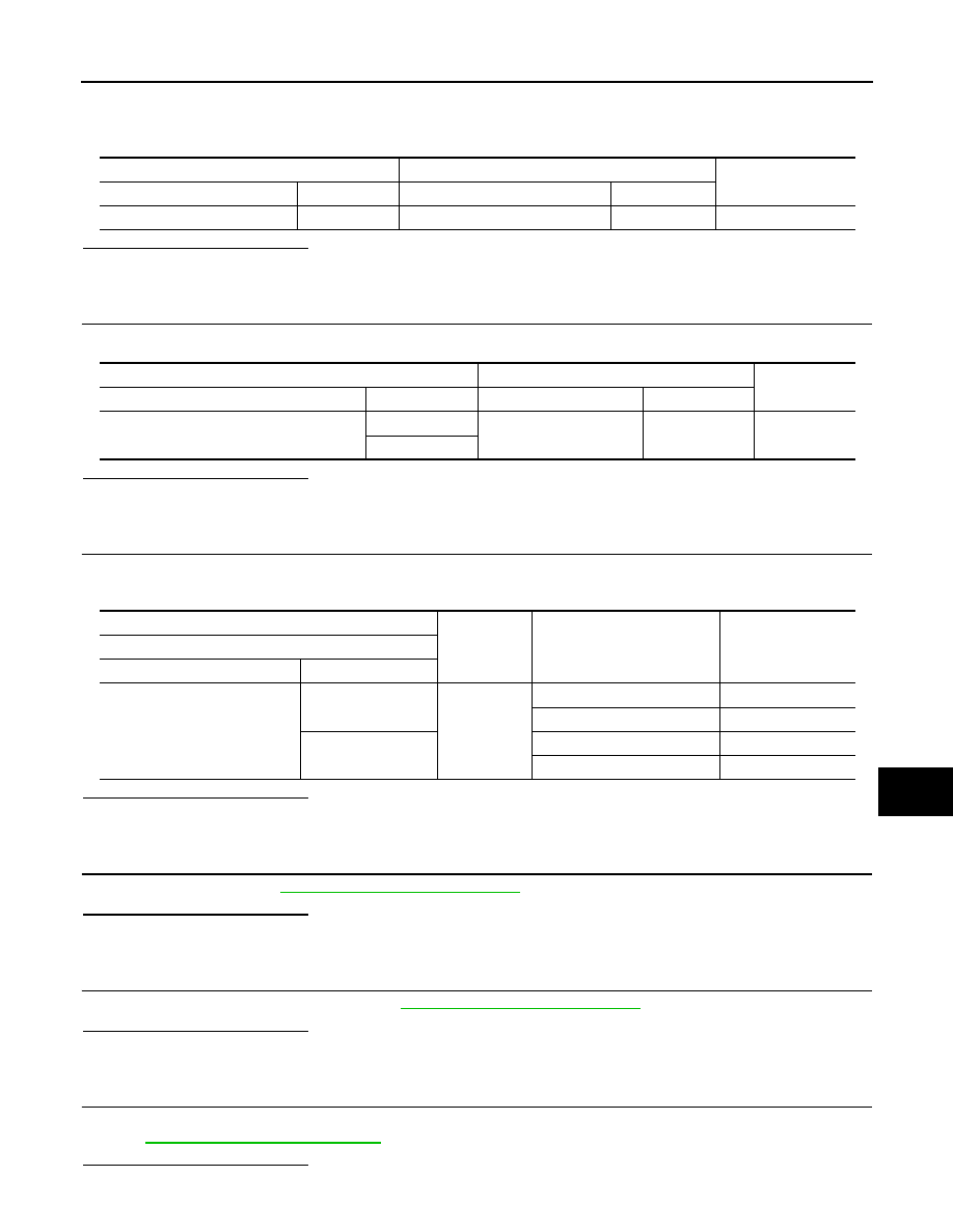
Condenser
Rear window defogger
Continuity
Connector
Terminal
Connector
Terminal
B75
2
B184
1
Existed
Fuse block (J/B)
Condenser
Continuity
Connector
Terminal
Connector
Terminal
B6
10G
B74
1
Existed
11G
(+)
(-)
Condition of rear window
defogger switch
Voltage (V)
(Approx.)
Fuse block (J/B)
Connector
Terminal
B6
10G
Ground
ON
Battery voltage
OFF
0
11G
ON
Battery voltage
OFF
0