содержание .. 348 349 350 351 ..
Nissan Murano Z51. Manual - part 350
WATER PUMP
CO-21
< REMOVAL AND INSTALLATION >
C
D
E
F
G
H
I
J
K
L
M
A
CO
N
P
O
WATER PUMP
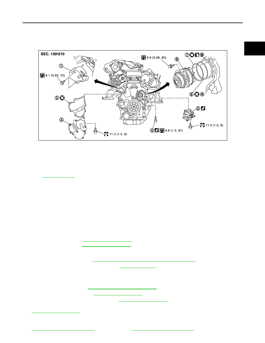
Exploded View
INFOID:0000000005518103
Removal and Installation
INFOID:0000000005518104
CAUTION:
• When removing water pump assembly, be careful not to get engine coolant on drive belt.
• Water pump cannot be disassembled and should be replaced as a unit.
• After installing water pump, connect hose and clamp securely, then check for leakage using the radi-
ator cap tester (commercial service tool) and the radiator cap tester adapter (commercial service
tool).
REMOVAL
1.
Remove the following parts.
• Air duct (inlet): Refer to
.
• Engine cover: Refer to
• Engine under cover
• Front road wheel and tire
• Splash guard (RH): Refer to
EXT-24, "FENDER PROTECTOR : Exploded View"
2.
Drain engine coolant from radiator. Refer to
CAUTION:
• Perform this step when the engine is cold.
• Never spill engine coolant on drive belt.
3.
Remove drive belt. Refer to
EM-17, "Removal and Installation"
.
4.
Remove idler pulleys. Refer to
.
5.
Remove reservoir tank of radiator. Refer to
.
6.
Remove reservoir tank of power steering oil pump with piping connected, and move it to aside. Refer to
.
7.
Support oil pan (lower) bottom with transmission jack.
8.
Remove engine mounting insulator (RH), engine mounting bracket (RH) and upper torque rod. Refer to
(2WD models) or
(AWD models).
1.
Timing chain tensioner (primary)
2.
Valve timing control cover gasket
(bank 1)
3.
Valve timing control cover (bank 1)
4.
Water drain plug (front)
5.
Water pump cover
6.
O-ring
7.
O-ring
8.
Water pump
A.
Apply engine coolant
B.
Identify with white mark
Refer to
for symbols in the figure.
JPBIA2460GB