содержание .. 308 309 310 311 ..
Nissan Murano Z51. Manual - part 310
C1143 STEERING ANGLE SENSOR
BRC-63
< DTC/CIRCUIT DIAGNOSIS >
[VDC/TCS/ABS]
C
D
E
G
H
I
J
K
L
M
A
B
BRC
N
O
P
Is the inspection result normal?
YES
>> GO TO 4.
NO
>> Repair or replace error-detected parts.
4.
CHECK STEERING WHEEL PLAY
Check steering wheel play. Refer to
.
Is the inspection result normal?
YES
>> GO TO 5.
NO
>> Repair or replace error-detected parts.
5.
CHECK DATA MONITOR
1.
Connect the ABS actuator and electric unit (control unit) harness connector.
2.
Connect the steering angle sensor harness connector.
3.
Check steering angle sensor signal. Refer to
BRC-63, "Component Inspection"
.
Is the inspection result normal?
YES
>> Replace ABS actuator and electric unit (control unit). Refer to
.
NO
>> Replace steering angle sensor. Refer to
.
Component Inspection
INFOID:0000000005517336
1.
CHECK DATA MONITOR
Select “ABS”, “DATA MONITOR” and “STR ANGLE SIG” in order with CONSULT-III, and check steering angle
sensor signal.
Is the inspection result normal?
YES
>> INSPECTION END
NO
>> Proceed to diagnosis procedure. Refer to
.
Special Repair Requirement
INFOID:0000000005517337
1.
ADJUSTMENT OF STEERING ANGLE SENSOR NEUTRAL POSITION AND CALIBRATION OF DECEL G
SENSOR
• After removing/replacing a steering angle sensor, be sure to perform the following procedure.
- Adjustment of steering angle sensor neutral position: Refer to
BRC-9, "ADJUSTMENT OF STEERING
ANGLE SENSOR NEUTRAL POSITION : Description"
.
• After removing/replacing an ABS actuator and electric unit (control unit), be sure to perform the following
procedure.
- Adjustment of steering angle sensor neutral position: Refer to
BRC-9, "ADJUSTMENT OF STEERING
ANGLE SENSOR NEUTRAL POSITION : Description"
.
- Calibration of decel G sensor: Refer to
BRC-10, "CALIBRATION OF DECEL G SENSOR : Description"
.
>> END
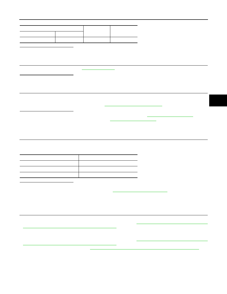
Steering angle sensor
—
Continuity
Connector
Terminal
M30
1
Ground
Existed
Steering condition
STR ANGLE SIG (DATA MONITOR)
Driving straight
−
3.5 – +3.5
°
Turn 90
°
to right
Approx.
−
90
°
Turn 90
°
to left
Approx. +90
°