содержание .. 211 212 213 214 ..
Nissan Murano Z51. Manual - part 213
AV
POWER SUPPLY AND GROUND CIRCUIT
AV-631
< DTC/CIRCUIT DIAGNOSIS >
[BOSE AUDIO WITH NAVIGATION]
C
D
E
F
G
H
I
J
K
L
M
B
A
O
P
POWER SUPPLY AND GROUND CIRCUIT
AV CONTROL UNIT
AV CONTROL UNIT : Diagnosis Procedure
INFOID:0000000005528757
1.
CHECK FUSE
Check for blown fuses.
Is the inspection result normal?
YES
>> GO TO 2.
NO
>> Be sure to eliminate the cause of malfunction before installing new fuse.
2.
CHECK POWER SUPPLY CIRCUIT
Check voltage between AV control unit harness connectors and ground.
Is the inspection result normal?
YES
>> GO TO 3.
NO
>> Check harness between AV control unit and fuse.
3.
CHECK GROUND CIRCUIT
1.
Turn ignition switch OFF.
2.
Disconnect AV control unit connectors.
3.
Check continuity between AV control unit harness connectors and ground.
Is the inspection result normal?
YES
>> INSPECTION END
NO
>> Repair harness or connector.
FRONT DISPLAY UNIT
FRONT DISPLAY UNIT : Diagnosis Procedure
INFOID:0000000005528758
1.
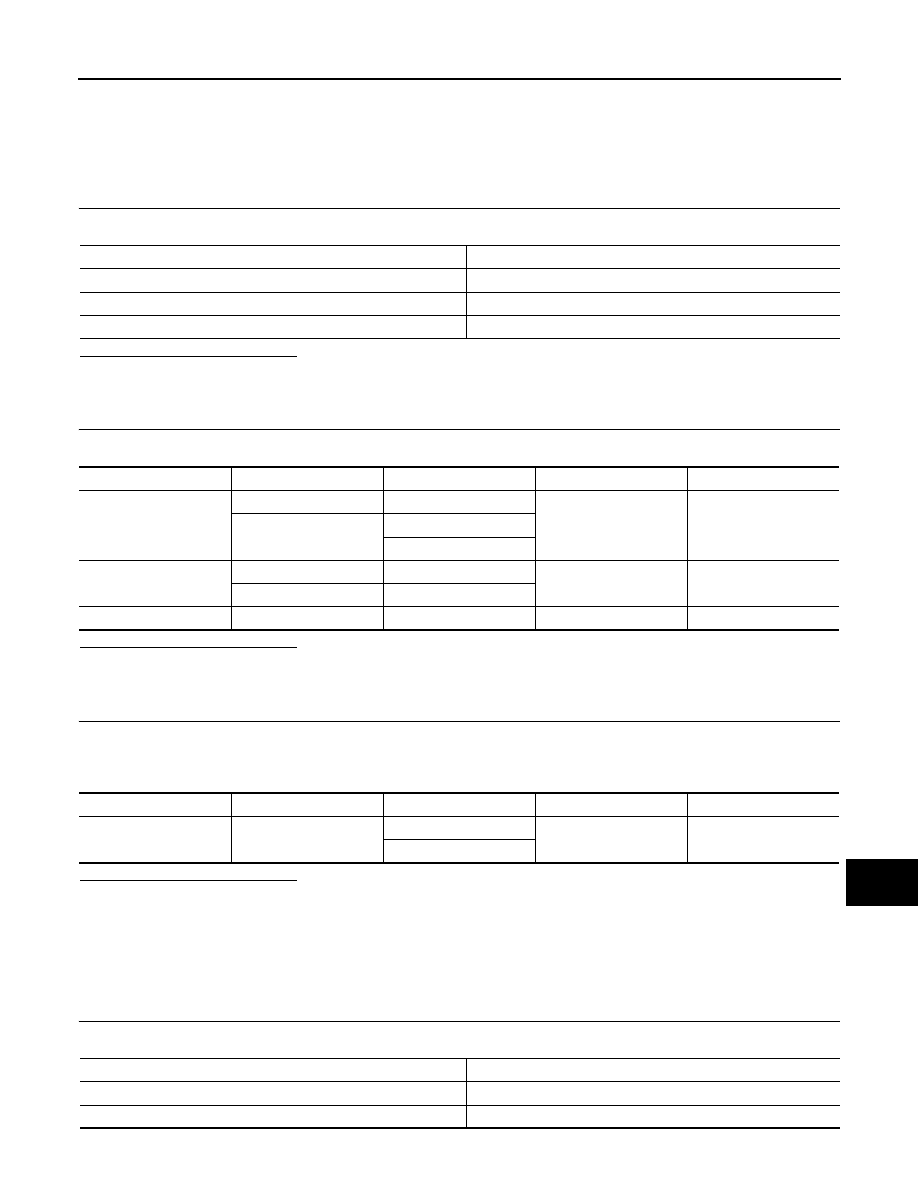
CHECK FUSE
Check for blown fuses.
Power source
Fuse No.
Battery
35
Ignition switch ACC or ON
19
Ignition switch ON or START
3
Signal name
Connector No.
Terminal No.
Ignition switch position
Value (Approx.)
Battery power supply
M144
19
OFF
Battery voltage
M145
22
24
ACC power supply
M144
7
ACC
Battery voltage
M145
25
Ignition signal
M145
35
ON
Battery voltage
Signal name
Connector No.
Terminal No.
Ignition switch position
Continuity
Ground
M145
21
OFF
Existed
23
Power source
Fuse No.
Battery
35
Ignition switch ACC or ON
19