содержание .. 1523 1524 1525 1526 ..
Nissan Murano Z51. Manual - part 1525
WT-38
< DTC/CIRCUIT DIAGNOSIS >
TIRE PRESSURE WARNING CHECK SWITCH
TIRE PRESSURE WARNING CHECK SWITCH
Component Function Check
INFOID:0000000005576002
1.
CHECK THE ILLUMINATION OF THE LOW TIRE PRESSURE WARNING LAMP
1.
Turn the ignition switch ON.
CAUTION:
Never start the engine.
2.
Short-circuit the tire pressure warning check switch connector terminal to the ground.
3.
Check that the low tire pressure warning lamp blinking.
Is inspection result normal?
YES
>> INSPECTION END
NO
>> Perform diagnosis. Refer to
Diagnosis Procedure
INFOID:0000000005576003
1.
CHECK TIRE PRESSURE WARNING CHECK SWITCH SIGNAL
1.
Turn the ignition switch ON.
CAUTION:
Never start the engine.
2.
Check the voltage between tire pressure warning check switch connector and ground.
Is the inspection result normal?
YES
>> Replace BCM. Refer to
NO
>> GO TO 2.
2.
CHECK TIRE PRESSURE WARNING CHECK SWITCH CIRCUIT
1.
Turn the ignition switch OFF.
2.
Disconnect BCM harness connector
3.
Check the continuity between BCM harness connector and tire pressure warning check switch connector.
4.
Check the continuity between BCM harness connector and ground.
Is the inspection result normal?
YES
>> Check BCM pin terminals for damage or loose connection with harness connector. If any items
are damaged, repair or replace damaged parts. Replace BCM. Refer to
NO
>> Repair or replace damaged parts.
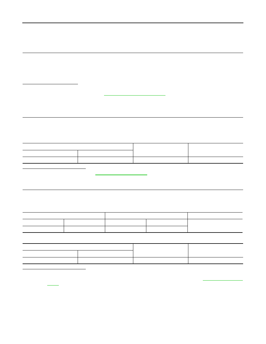
Tire pressure warning check switch
—
Voltage (Approx.)
Connector
Terminal
M19
1
Ground
11.8 V
BCM
Tire pressure warning check switch
Continuity
Connector
Terminal
Connector
Terminal
Existed
M123
149
M19
1
BCM
—
Continuity
Connector
Terminal
M123
149
Ground
Not existed