содержание .. 1493 1494 1495 1496 ..
Nissan Murano Z51. Manual - part 1495
WCS
DIAGNOSIS SYSTEM (BCM)
WCS-21
< SYSTEM DESCRIPTION >
C
D
E
F
G
H
I
J
K
L
M
B
A
O
P
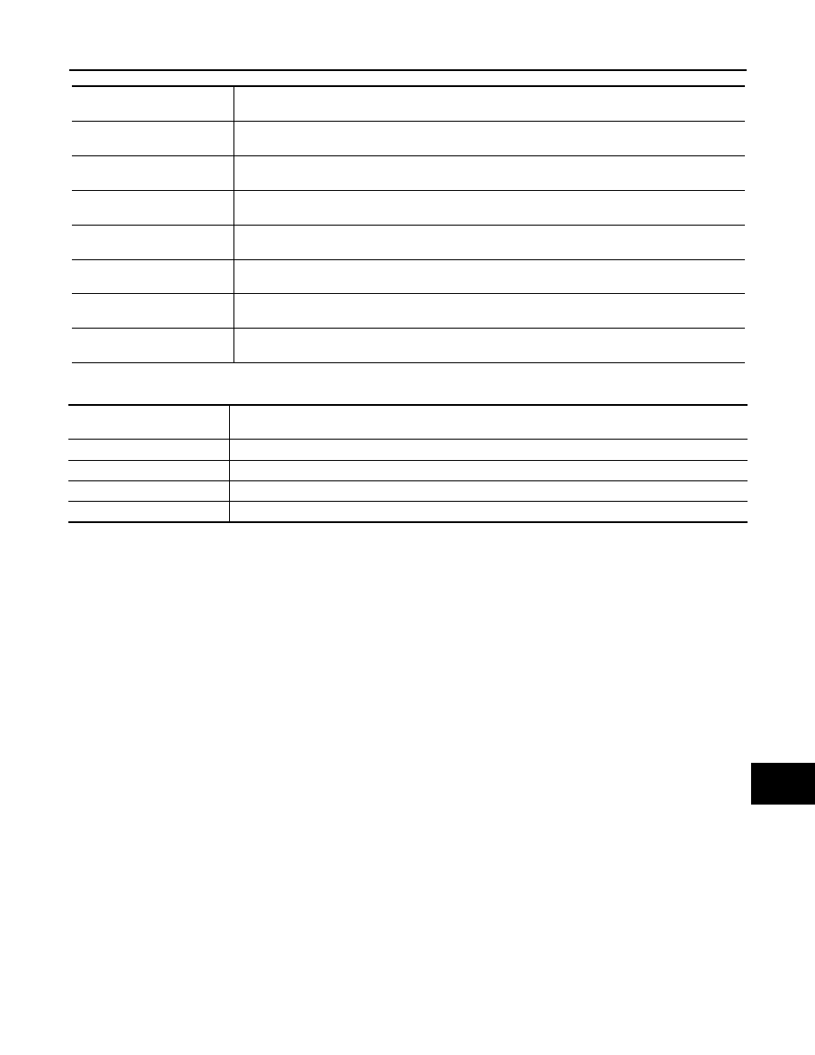
ACTIVE TEST
Display item
[Unit]
Description
PUSH SW
[On/Off]
Status of push button ignition switch judged by BCM.
UNLK SEN-DR
[On/Off]
Status of unlock sensor judged by BCM.
VEH SPEED 1
[Km/h]
Value of vehicle speed signal received from ABS actuator and electric unit (control unit) with CAN
communication line.
KEY SW-SLOT
[On/Off]
Status of key slot judged by BCM.
TAIL LAMP SW
[On/Off]
Status of each switch judged by BCM using the combination switch readout function.
FR FOG SW
[On/Off]
Status of front fog lamp switch judged by BCM.
DOOR SW-DR
[On/Off]
Status of driver side door switch judged by BCM.
Display item
[Unit]
Description
IGN KEY WARN ALM
The key warning chime operation can be checked by operating the relevant function (On/Off).
SEAT BELT WARN TEST
The seat belt warning chime operation can be checked by operating the relevant function (On/Off).
ID REGIST WARNING
The ID regist warning chime operation can be checked by operating the relevant function (On/Off).
LIGHT WARN ALM
The light warning chime operation can be checked by operating the relevant function (On/Off).